Hi does anybody have the correct wiring diagrams for my 2008 Range Rover Vogue TDV8 with the 3.6 L engine as all the ones that are available on the internet either free or paid do not appear to be relevant to this vehicle. This also includes the layout of the fuse boxes. I need these as I am trying to track down an electrical problem that is causing my vehicle not to turn over / start. I have found a possible clue in that my fuse voltages on F31 - F38 appear to be giving 3.2 volts but I cant track where these fuses get there power without the correct cct. The earlier range rover wiring diagrams are no help as they are different to my vehicle,
You are using an out of date browser. It may not display this or other websites correctly.
You should upgrade or use an alternative browser.
You should upgrade or use an alternative browser.
Wiring Diagram for 2008 Range Rover Vogue TDV8
- Thread starter ALIRAIL
- Start date
This site contains affiliate links for which LandyZone may be compensated if you make a purchase.
Welcome")
I have 2011 so probably no good.
You can sign up for a weekend (costs) to TOPIX and download all you want for the whole car, It takes a while, but you get all the info you need.
What do those fuses power out of interest? I will have a look at the manuals I have and let you know if I can find anything.
Do you have diagnostics it would help alot.
J
- Posts
- 6,224
- Location
- North Manchester
This is from a 2007 to 2010 manual. Both fuses seem to be fed by the ignition switch which I believe is a known issue.


Hi Everybody, many thanks for the help so far, the fuses that appear to have 3.2 volts across them whether they are in or out are F31 - Eng Sys Fuse, F32 - Adaptive Lights, F33 - Traction, F34 - Seat AC Fan, F35 - Dissent Control System, F36 - Park Brake and F38 - ABS. In addition when the fault occurred I also lost my 12 volt Cigar Light Sockets and found this was because the relays on the rear fuse panel were only being supplied with 3.2 Volts instead of 12 volts and I am assuming this is the same feed that is also suppling the fuses from the IGN ??? As indicated earlier my problem to help me track down the fault is that none of the Land Rover Technical Docs appear to cover the wiring of this particular vehicle and it is therefore impossible to fault find. Even the layout of the fuses in the glove compartment are different to all the docs on the internet and the Land Rover Electrical diagrams.
What I would like to know is where does the 3.2 volt feed come from and why is it 3.2 volts ? I am assuming it comes from the Ignition feed and this is the rout of all my problems.
Alastair
What I would like to know is where does the 3.2 volt feed come from and why is it 3.2 volts ? I am assuming it comes from the Ignition feed and this is the rout of all my problems.
Alastair
- Posts
- 6,224
- Location
- North Manchester
The first diagram I posted shows 2 feeds to the ignition (fuses 62 & 25). The second diagram shows fuse 35 (numbered 21 on the diagram) so at least 3 of the fuses you mention are ignition fed.
You could have a bad connection in the ignition switch itself, I would start with fuse 62 and see what you have there.
You could have a bad connection in the ignition switch itself, I would start with fuse 62 and see what you have there.
- Posts
- 6,224
- Location
- North Manchester
So far I have found the following fuses fed from the ignition, 3, 6, 7, 31, 32, 35, 36, 38, 39, 41 but there are 183 search results for ignition switch so I've stopped looking for more.
The first diagram I posted shows 2 feeds to the ignition (fuses 62 & 25). The second diagram shows fuse 35 (numbered 21 on the diagram) so at least 3 of the fuses you mention are ignition fed.
You could have a bad connection in the ignition switch itself, I would start with fuse 62 and see what you have there.
Hi many thanks for the help so far. From your reply you indicated that you have a 2007 to 2010 manual can you tell me why I might be able to get one from. I have already checked the voltage at the fuses in the Engine management box in the engine bay and nothing appeared to be wrong (0v or 12 volts).So far I have found the following fuses fed from the ignition, 3, 6, 7, 31, 32, 35, 36, 38, 39, 41 but there are 183 search results for ignition switch so I've stopped looking for more.
- Posts
- 6,224
- Location
- North Manchester
Sorry I can't remember where I downloaded it from and it's 72meg so I can't email it. if you google "Range Rover L322 Workshop Manual 2007-2010 download" it comes up with a few links.
If you have 12v going to the ignition and 3.2v coming from it that to me points to a faulty switch.
If you have 12v going to the ignition and 3.2v coming from it that to me points to a faulty switch.
Hi Everybody
Firstly thanks for the help that everybody has given me over the past few days and I am pleased to say that I have solved the problem and my Range Rover is now running fine apart from the (4 + 4) hours of work that I had to put in to gain access to the ignition switch the total cost of the repair was 2 pence. Anyway for anybody who is interested here is the step by step analysis and solution.
The Problem
- Not able to start or turnover diesel Eng.
- Numerous diagnostic warnings, many related to inter module Can Bus Communications
- Many none engine, gearbox, Suspension, ABS and SRS functions still fully operational (Lights (Interior / exterior), Sun Roof, Radio / Media, Horn, Seat Adj, Steering Adj, Remote Locks, Mirrors and Windows.
- Noticed I had also lost Cigar Lighters / Aux 12 volt Plugs.
- Checked Battery (found lose clamps and low voltage)
- New Battery and Tightened Clamps - Still Same Problem
- Checked all fuses / fuse links - Engine ECU box, Passenger Glove Comp and RHS Rear Fuses = All OK
- Removed and Checked Rear Relay Operation for cigar lighter and coil voltages, found relay coil voltage for cigar = 3.6 volts in IGN position
- Measured DC Voltages across all fuses to check for either +12 V or O V with Ignition Key in Off, Aux, Ign and Cank Position (Found Fuses * to * only read 3.6 volts in IGN position.
- Removed fuses * to * / rear relays and checked to see if voltage still showed 3.6 volts on common end of fuses to determine if something might have been pulling the voltage down from 12 volts to 3.6 volts (If so common rail should go back to 12 volts when fuses are removed, With the fuses / relays removed the supply voltage was still 3.6 volts.
- Established all these fuses and relays are driven from the output of the Ignition Switch IGN contact Green Wire.
- Put all the fuses and relays back in the correct positions and with the Ignition in the IGN position using a link wire connected the common of fuses * to * to +12 volts and hey presto everything came live. With the link still in position connected diagnostic computer to determine if CAN Bus was operational and clear all errors (note if you dont clear the errors these will stop the engine from being started.. Moved Ignition Switch to Crank and the engine started,
- Conclusion that there is either a break in the IGN Cable or the Ignition Switch has failed.
- To get to the Ignition Switch it is necessary to remove lots of front facia parts (Passenger Side panel, Floor Panel, Air Vent, Lower and Glove Compartment) which then gave me access to the passenger fuse tray. I was then able to check if the 3.6 volts was being caused by the Ignition Switch by disconnecting the main multiway connector which has the large Green (IGN) Cable and checked if the 3.6 volts was still present with Ignition Switch in the IGN position (found still at 3.6 volts with the connector unplugged from the rear of the fuse panel) fault must therefore be more towards the Ignition Switch.
- Based on the results of 1 continued to stripe the front facia to access the Ignition Switch (Passenger Upper Glove Compartment / Air Bag Asm, Centre Air Vent, Driver Floor, Driver Air Bag Asm and Side Panels, Driver Air Vent, Upper Instrument Cover, Centre Console / Glove Switch and Ignition Switch Cover) to gain access to the Ignition Switch Cover Plate).
- Removed the two Ignition Cover Retainer Screws to gain access to Ignition Switch.
- Removed the two Ignition Switch Retainer Screws to free switch from cover plate and then disconnected gear level mechanical linkage.
- Used volt meter to check if the Green IGN wire had 3.6 volts (Yes) therefore fault is either the Ignition Switch Contact or Connector.
- Disconnected cable harness from rear of Ignition switch and then Ignition Switch Contact block (held in by two grub screws) and test contacts under load found to be OK
- Review the IGN Green Wire Harness Crimp and it appeared to look like a poor contact and based on the fact it is not possible to easily pull the contact crimp out of the connector block, I decided to see if I could squeeze the crimp with some long nose pliers. This restored the IGN Green Wire Voltage back to 12 volts instead of 3.6 volts but waggling the connector / switch asm resulted in intermittent voltage levels.
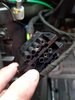
- Finally solve the poor connection issue by using some braided wire 15 mm long and inserting it into the female portion of the crimp (see attached photo) and carefully installing the connector back into the switch asm. After much shaking and waggling the 12 volts on the IGN Cable and back at the fuse box was stable.
- Reassembled all the facia parts and 4 hours later turned the Ignition On and everything worked correctly and the engine vehicle is still running after 100 + miles.
In closing I would like to again thank you all for your support and to Dave Hart for helping me with the actual vehicle. Also I am still concerned that I have still not found the correct 2007 - 2009 wiring diagrams for my Range Rover 3.2 V8 Vogue which appears to be different from all the earlier 3.2 RR V8.
Alastair
Alastair
brianp38dse
Well-Known Member
- Posts
- 20,094
- Location
- heathrow
Well do on sorting that one out and posting the fix, as so many people never post the fix which is very annoying when you find a post with your problem and read to the end of the post to be left with out a fix- Posts
- 6,224
- Location
- North Manchester
Glad you got it sorted. At least it was one of the quicker things to fix
Hi AliHi Everybody, many thanks for the help so far, the fuses that appear to have 3.2 volts across them whether they are in or out are F31 - Eng Sys Fuse, F32 - Adaptive Lights, F33 - Traction, F34 - Seat AC Fan, F35 - Dissent Control System, F36 - Park Brake and F38 - ABS. In addition when the fault occurred I also lost my 12 volt Cigar Light Sockets and found this was because the relays on the rear fuse panel were only being supplied with 3.2 Volts instead of 12 volts and I am assuming this is the same feed that is also suppling the fuses from the IGN ??? As indicated earlier my problem to help me track down the fault is that none of the Land Rover Technical Docs appear to cover the wiring of this particular vehicle and it is therefore impossible to fault find. Even the layout of the fuses in the glove compartment are different to all the docs on the internet and the Land Rover Electrical diagrams.
What I would like to know is where does the 3.2 volt feed come from and why is it 3.2 volts ? I am assuming it comes from the Ignition feed and this is the rout of all my problems.
Alastair
Hi ALIRAIL I HAVE THE SAME PROBLEM WITH MY RANGE ROVER L320 TDV8 3.6L AS YOUR RANGE ROVER PLEASE IF YOU CAN ASSIST ME ON WHICH FUSE AND WIRE DID YOU FIX OR WORK TO FIX THE PROBLEM AND THE PHOTO OF THE WIRE LOCATION I WILL APPRECIATE IT THANKSHi Everybody, many thanks for the help so far, the fuses that appear to have 3.2 volts across them whether they are in or out are F31 - Eng Sys Fuse, F32 - Adaptive Lights, F33 - Traction, F34 - Seat AC Fan, F35 - Dissent Control System, F36 - Park Brake and F38 - ABS. In addition when the fault occurred I also lost my 12 volt Cigar Light Sockets and found this was because the relays on the rear fuse panel were only being supplied with 3.2 Volts instead of 12 volts and I am assuming this is the same feed that is also suppling the fuses from the IGN ??? As indicated earlier my problem to help me track down the fault is that none of the Land Rover Technical Docs appear to cover the wiring of this particular vehicle and it is therefore impossible to fault find. Even the layout of the fuses in the glove compartment are different to all the docs on the internet and the Land Rover Electrical diagrams.
What I would like to know is where does the 3.2 volt feed come from and why is it 3.2 volts ? I am assuming it comes from the Ignition feed and this is the rout of all my problems.
Alastair
Similar threads
- Replies
- 0
- Views
- 402
- Replies
- 2
- Views
- 627
- Replies
- 97
- Views
- 4K