Land-rover hydraulic winch re-build and fit.

This site contains affiliate links for which LandyZone may be compensated if you make a purchase.

Erubus

Member
Posts
65
Location
Perthshire
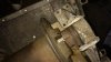
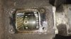
Hi guys. In the dying days of landrovernet I bought a couple of winches off of another member. ONe of them is a land-roer hydraulic winch. Much the same as the MKII hydraulic winch but older. I have been unable to find much info on it all to be honest. Can find a couple of exploded drawings of the mkII but nothing at all on the mkI.

The other winch is a capstan which is missing the engine side of the drive and which will be a seperate thread when I eventually get the parts for it - and another series truck to putit on :D (shhhh, don't tell the OH)

I have been working on the series three to get it through its MOT, which it failed last week. The brakes have always been terrible as they were fitted with a master cylinder off of a 90. They only just scraped a pass at abot 532% efficiency every time it was tested, so I finally bought a new, proper 88" dual circuit servo MC and it failed miserably on less than 30%, so have been trying to get them to work better. I got ****ed off in the end and started to put the winch together.
 
So first thing was to look at the pile of bits and see what I had. It was meant to be complete but in bits. Heres what I had..... (see first thumbnail)

I laid all the parts out to see what I had. Without a manual I had to pretty much guess where everything went, along with an exploded drawing of the mkII which I found online. Although it was meant to be complete, there are a couple of prety essential items missing. The winch consists of two cast alloy end pieces containing the bearings and drive gears and they are held together by two round bars fitted, one at the front and one at the back. These parts are missing, as is the lever that selects freewheel, for spooling out the cable and locked for actual winching. The two bits of round bar will be easy to knock up on the lathe once I have built it up to get the dimensions. the selector lever will be a little trickier but not difficult by any means.

The parts were all covered in a good layer of surface rust, so the first order of business was to clean it all up with the wire bruch (powered) and then get building. To anyone else building one of these winches at any point... here was my first mistake. I built up the worm drive gear first then tried fitting the mainshaft and then the large bronze wheel. This doesn't work. The shaft and bronze wheel needs fitting first, then the worm drive gear goes in afterwards. heres what I have got so far....
IMG_20170826_175020180.jpg
IMG_20170826_181605730.jpg
IMG_20170826_175020180.jpg
IMG_20170826_181605730.jpg
IMG_20170826_191623627.jpg
IMG_20170826_192845606.jpg
IMG_20170826_195200869.jpg

The drum is only test fitted at the moment. I haven't yet decided whether to paint the whole thing up and make it "as new" or to leave it looking well used. Im leaning towards leaving it looking as is just now as the truck is looking pretty rough at the moment. When I get round to redoing the paintwork on the truck I will take the winch apart nd paint it all up as well.

I'll be going at it again on the brakes today - I have got it stopping quite nicely but the NSF brake is binding badly so need to keep adjusting away and get it right. Hopefully I will be ableto get some more work done on the winch afterwards.
 
Well I finished off a few wee odd jobs on the landy to get his year's ticket and had an hour or so spare. So went at it again on the winch. I fitted the drum yesterday then realised that I had put a collar on in the wrong place. Unfortunately it was almost an interference fit and took quite some persuasion to get back off again! Once off, the drum went back on, followed by said collar, two keys, dog clutch, bearing and end casting.

Then it was the bearing retainer and band brake drum for the worm drive. This was followed by the hydraulic motor. I wasn't able to turn the motor by hand, so I will probably take it back off and investigate further. I should imagine that i shouldbe able to turn it fairly easily. Some more pics of the progress

IMG_20170828_152132591.jpg
IMG_20170827_175731873.jpg
IMG_20170828_152125569.jpg
 

Attachments

  • IMG_20170828_152141575.jpg
    IMG_20170828_152141575.jpg
    206.9 KB · Views: 161
  • IMG_20170828_152141575.jpg
    IMG_20170828_152141575.jpg
    206.9 KB · Views: 136
I finished off the shaft yesterday to fit the back end of the winch together and also cut some steel plate to make a bracket to attach the winch onto the crossmember. I was looking for 1/4" plate but could only find 10mm. A bit heavy but it's not going to bend that's for sure! I'd put the top cover of the winch on incorrectly. It is meant to to house a band brake but the PO said it had fell apart. When I took it off I gave the thing a spin roud and with the little bit extra leverage the winch turned smoothly and easily so no need to strip the hydraulic mtor after all which is nice.

I had test fitted the winch to the front of the truck a few days ago and it didnt seem like it was going to fit. The brackets it came with were miles off. The winch had come off a 101 though and the PO was hoping to fit it to a defender so the brackets would have been for either of these. Length-wise though, it looked like it was going to stick off the end of the bumper by about half an inch. With the new stay bar on the back though it looks like its going to fit perfectly.

The problem I have now is do I fit the winch so that it is central to the grille, which would make the drum itself off-centre, or do i fit the winch off centre so that the drum is central? It's real battle for my OCD! Ive been looking at pics online and have seen them fitted both ways. Have been looking at capstans as well and they also seem to be fitted with the bollard off centre. There is a big fairlead assembly that fits on the front, it has a cut-out for the starting handle hole, this shold give me a good idea of which way it's meant to fit.

IMG_20170905_182323815.jpg
IMG_20170905_182625506.jpg
IMG_20170905_184617038.jpg
IMG_20170905_184630426.jpg
 
agreed. I'm glad I didnt paint it, it would have looked very out of place. I do intend painting the whole truck at some point soon, although I have been saying that for a few years now! When I do the rest of the truck I'll do the winch as well. I had a little spare time before a hospital appointment so I decided on the position and drilled the holes in the bumper. The bggest drill bit that I could find was 10.5mm. Fine if I was going for m10 bolts but I'd rather go for m12. The original ones are, I think, 7/16 or1/2 UNF. Holes are in the right place though so an easy job to bore them out a little larger to fit bigger bolts. I went for winch in centre with drum slightly offset in the end. Looking at the serial number on the hydraulic motor, it looks like the winch is a 1962 model, certainly a mk1 anyway.

IMG_20170906_113739966.jpg
IMG_20170906_120534776.jpg
 
Always liked the look of an old winch , purposeful, fancied a capstan until I saw it take a couple of layers of skin off when the rope slipped .
 
Had a go at fitting the spool valve and pump yesterday. Spent quite some time fitting the spool valve because i made a bit of an arse of it to be honest. Looks OK in the end though. The reall problem came when I fitted the pump though. It doesn't fit. The clutch collar that locks the PTO onto the gearbox mainshaft just falls right off. The winch was apparently fitted to a 101, so presumably the male part of the dog clutch sits further out on that gearbox and there is a different casting on the pump to make up the different size. I'm pretty gutted to find such a major problem so close to the end of the build. These things are like hens teeth so I'm unlikely to find one for anything ither than loads of money, or one that isnt part of a complete set or complete pump. Ive posted a thread in the series section, hopefully someone else has one of these PTOs and can tell me the thickness of the casting which is different. If I can get that dimension I can cut mine down and TIG weld it back together. here are some pics of the progress so far and the pump fitted with the clutch collar falling off the end of the shaft.

I have also attached a diagram of the hydraulic set up with the casting arrowed. you can see it is much shorter in the diagram.

The eagle eyed among will notice that I have the spool valve upside down. I couldnt get ot to fit the other way round, it fouled on the top of the transfer box. It is also the same way that it is fitted in this video:

IMG_20170909_161458610.jpg
IMG_20170909_161515893.jpg
winch diagram2.jpg
IMG_20170909_162714772.jpg
 

Attachments

  • IMG_20170909_162708346.jpg
    IMG_20170909_162708346.jpg
    409.7 KB · Views: 151
Back
Top