Inertia switch wiring

This site contains affiliate links for which LandyZone may be compensated if you make a purchase.
If it's going in the spare wheel well, it is supposed to be level yes.

If it isn't the valve might not work as expected and allow over filling. If it's not off by much I shouldn't worry about it. I've never seen them get a spirit level out at the inspection.

I bought a length of stainless threaded rod to mount my tank. Using nuts and washers, it allowed me to make small adjustments to make it perfectly level. Not worth the bother though I expect. As I say I've never seen anyone check it closer than by eye.

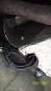
With regard to the fuel pipe, you could ask here LPG Discussion Forum for advice on routing. Rossko on there works for Blaze Autogas and knows all about fitting systems to Range Rovers. He'd know best.

I'm not very happy with how I've routed mine and will change it one day...when I get the time!
 
Last edited:
MrGorsky,
tank spacers ordered, and I'll get to look underneath to see a prospective route! Where it gets too close to the exhaust I'll make up some heat shields.Looking forward to completing the installation - now with only the pipes, wires and tank to fit. Checked the bonnet shut clearances the other day and they seem fine with no fouling of the injectors - our 4.0 has had the sound proofing removed to gain clearance. I also ran the engine up and the vapouriser got warm quite quickly so the positioning on the passanger side suspention turret is OK, its surprising that trying to get it lower than the header tank was so difficult. Filter shut off solenoid was fitted in the same location. ECU is fitted to the drivers side suspension turret with again a heat shield just in case. Probably another week before I can hook up the computer!
 
My vaporiser is in the same place as yours. I didn't even consider it might be higher than the header tank! The coolant is under pumped pressure though so I suppose any air would be driven out once you rev up a bit.

I left my bonnet sound proofing in. The injectors just make a little indentation in it. I mounted 6 of my my injectors in a row across the front of the plenum just to the right of the alternator. It'll be different for you because I was reusing my old Jag kit (for a 6 cyl car), so the fitting of it was a little different to standard. I did make sure that they weren't higher than the 4.6 bit of the plenum though.

Have you thought about putting your gas ECU in the old GEMS ECU box behind the battery? Nice and protected in there, and unless you've used it for something else, it should be empty. I've heard a few THOR people do that. It certainly makes sense.
 
Yes I looked at the old GEMs ecu 'box' on the battery, but thought I might need to get at the connections for the ecu so made up a bracket for it on the drivers side suspension mounting. Its quite slim and can be removed to get at the steering shaft should I have too. Other little problems were the fitting of the MAP sensor - which has to be higher than the outlet from the Inlet manifold - so this got fixed to the rear bulkhead. Getting back to the tank - I'm just fitting that now and to say the floor pan is thin is an understatment - still got the round spacer washers (3mm), and 50mm/3mm external washers so all should be OK. Its a 4 bolt mount tank with the side valve on it so hopefully that'll be in by tonight. I've trial fitted it to pull the forward mountings level on the floor pan. Just the exit holes for the vent pipes and we're close to getting there!
I've also got some strip rubber to 'insulate' the tank from the mountings. The pipe run still looks like fun though.
 
I put my exit holes for the pipework at the rear, so they come out just under the bumper.

HERE IN FACT

The pipe run is some fun. Mine goes out the wheel well, then along the bumper to the nearside, then kind of between the bodywork and the chassis (to avoid the exhaust) and then along the chassis rail and up in to the engine at the front. As I said I'm not very happy with how I've done mine, a better way would be to go along the inside of the chassis rail I think, but I'm not sure how you'd deal with the exhaust.
 
Hi Mr Gorsky,
well, one of those days -it all took longer than expected, well, we all have them! Just about got the tank in, and as you suggested, as level as I can get it, just off dead level unfortunatley. This will require the boot floor to be packed to fit and not interfere with the tank. ( Its a 92 litre tank so slightly deeper than normal) Tank hardware went on and so no more time left to do anymore today.
I'm going to get the system piped up over the next couple of days, then it'll be off to get it certificated early next week hopefully. Managed to get the nearside rear heat shield off so that will give me the in for the tank end, and I think I'll run it on the lower outside edge of the LH chassis rail, going round any obstructions. This should allow me to take it up the front body mount and on top of the chassis leg to the filter valve/ vapouriser.
Saw the pick up photo, yep, thats where mines going. I also read the bit on spud placement - very helpful, I managed to get mine fitted in the same way. To keep the pipes a decent length I just removed enough (for two pipes worth) from the available webs between the ram pipes. Not that the GEMS owners have to go that far - and can get much shorter pipes on!
Once its sucessful I'll try to get a couple of photos of the installation on here ( if I can find out how).
Thanks for your continued help.
 
Interesting posts gents, I am going to embark on fitting a kit to my Thor engined 38. Got the tank already, interesting the tank came from a friends 38 running a closed loop single point system and the feed pipe came out of the front of the wheel well just behind the axle. worse still was that it was a bare pipe from the tank through the gromit to the outside world.....not good and meant to be a pro-fit system....
 
john,
good luck with the installation, its a bit fiddly to say the least, and I had the benefit of another car to look at. I'm not looking at getting it certified until the late part of next week, so I'll try and get some photos on once I know what I've done works, may help you out planning where and how to put things. Now I'm not sure about open / closed loop systems (?), but I know when I ordered the Kit the suppliers needed to know exactly what model I was putting it on. Are you sure that it will work on a later car?
Either way as Mr Gorsky said the LPG Forum is a mine of information.
 
Hi All,
car done and now running well on LPG. Thanks for all the help. Install was involved and luckily I had the time to think of where to put things without having to get her back on the road. Will sort out a few pictures which may give anyone who's thinking of it a few pointers - the Thor inlet manifold can be an interesting problem. All the best.
 
Hi All, as promised, some photos of the installation. Photo 1 (2) is the modification to the Thor manifold, by removing the areas of webbing I managed to secure a route for the LPG pipes ( max 2 per hole) this kept them around 30cm the other ends of the pipes are on the spuds in the inlet manifold I had to be very careful not to break into the runners as this material was removed. Photo 2 is the finished article, I had to make up brackets for the injectors to sit on, LH are attached to the 2 threaded holes on the far L of the Plenum, RH are on the 2 main LH bolts for the Plenum. I put the MAP sensor in the position shown as it was supposed to be higher than the vac take off from the plenum. Photo 3 is the tank install, as Mr Gorsky advised.Photo 4 is the vapouriser and solenoid, mounted on the RH Turret. Photo 5 is the Heat shield I made up to sit on the existing one so the LPG pipes are protected from the exhaust pipe - sorry about the photo. Thanks go out to Mr Gorsky, and all the guys at Tinley Tech, without whom this would have been a real headache. As this was the first (and as they're all on LPG now, probably the last), time I've tackled anything like this - they were all invaluable. :)
 

Attachments

  • Picture 1 (2).JPG
    Picture 1 (2).JPG
    197.2 KB · Views: 163
  • Picture 2.JPG
    Picture 2.JPG
    288.9 KB · Views: 198
  • Picture 3.JPG
    Picture 3.JPG
    152.6 KB · Views: 144
  • Picture 4.JPG
    Picture 4.JPG
    107.5 KB · Views: 181
  • Picture 5.JPG
    Picture 5.JPG
    575.7 KB · Views: 135
Back
Top