In Car Multigauge - project

This site contains affiliate links for which LandyZone may be compensated if you make a purchase.

Bennehboy

Well-Known Member
Posts
2,202
Location
Huddersfield
EDIT - 13 Jan 2017

The source code for this project can be obtained from here -> https://github.com/BennehBoy/LRDuino

/EDIT


I'm working on a little project so I can monitor some additional sensors in my D2.

To start with it will cover EGT, Boost, Oil Pressure, Oil Temp, and Transfer Oil Temp. It's pretty easy to monitor pretty much anything. At present only the EGT sensor (K type thermocouple) will require any extra circuitry (I think!).

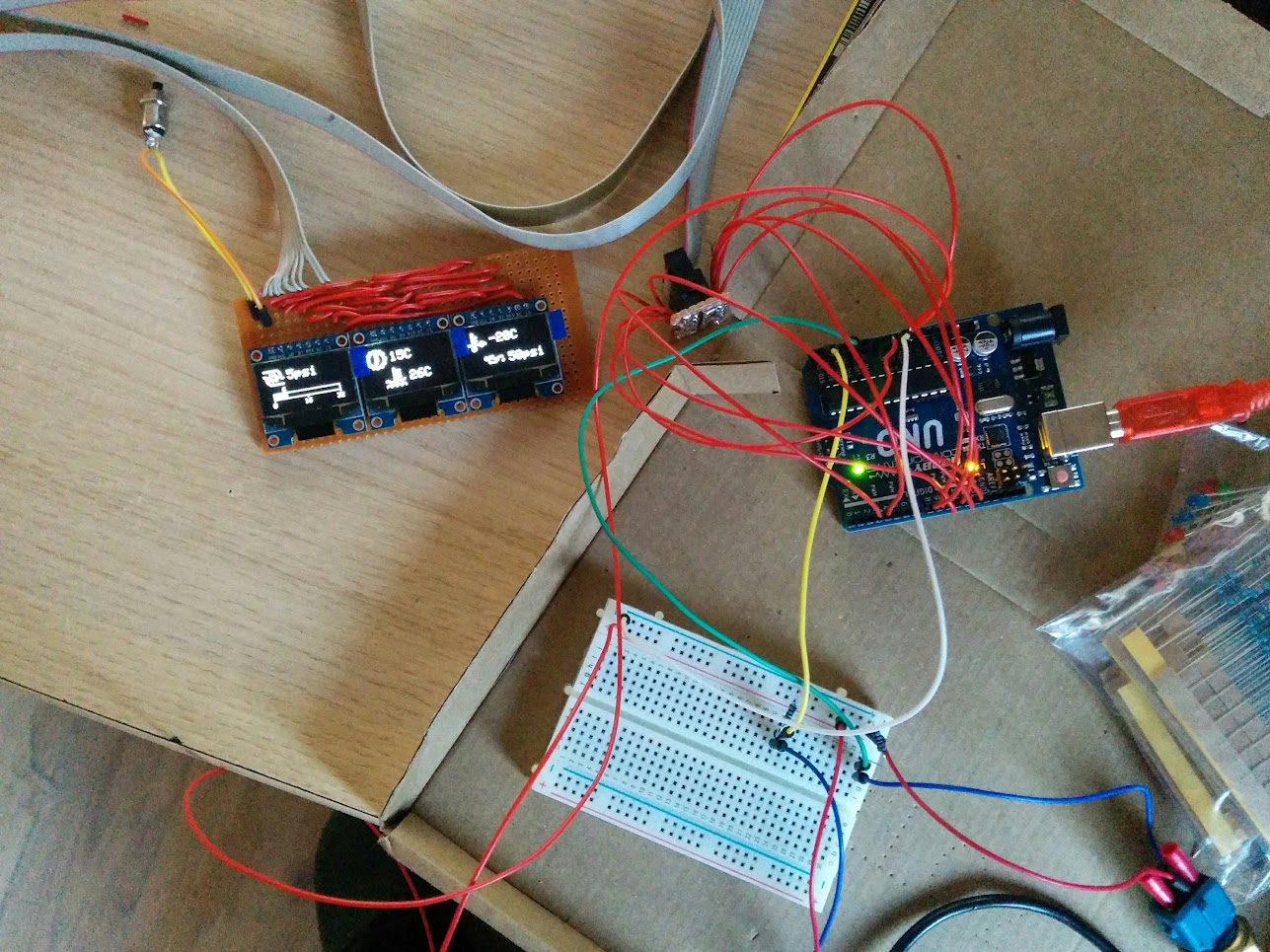
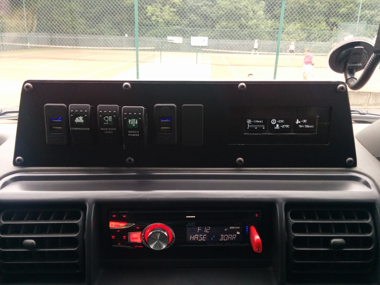
So anyway it's powered by an Arduino and uses 3 small OLED displays (coming to a princely sum of about 15 quid), the left hand display will have a large gauge, and the other 2 displays will show 2 text based sensor readings.

So far (with about 2-3 hours work) I've got 4 gauges with graphics to rotate around the displays on command (via a pushbutton). The idea being that you rotate the sensors round until the one you want to see most clearly is on the big gauge display.

Here's a little vid I made:


There's some wrapping artefacts I need to clean up when the pressure values are displayed at the bottoms but that should be easy to sort.

Still to do:
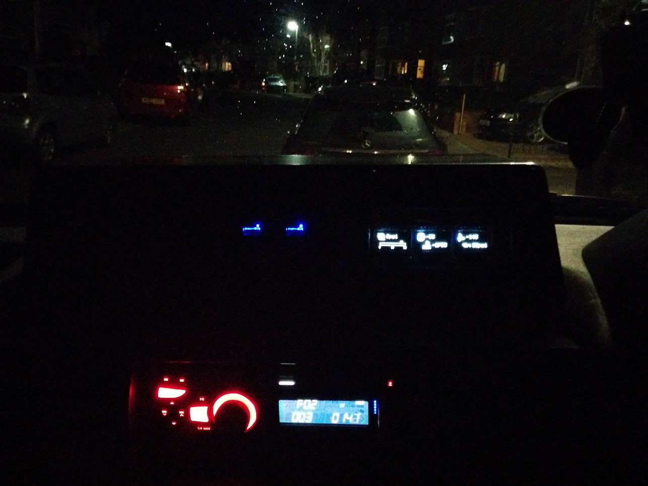
Main gauge gfx on left hand display
Sensor/Input handling on the analogue pins
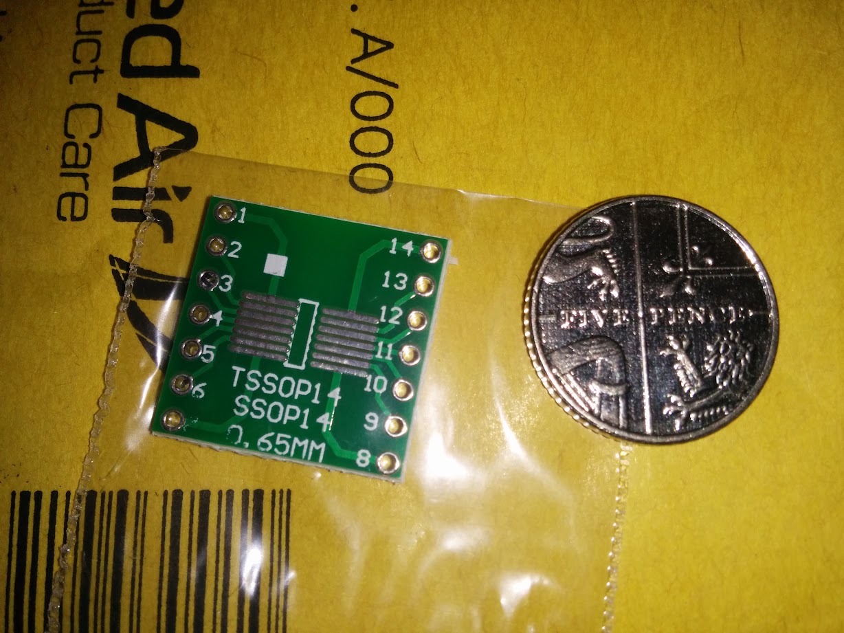
Electronics for sensors (EGT thermocouple needs an IC and decoupling), not sure about oil pressure yet.
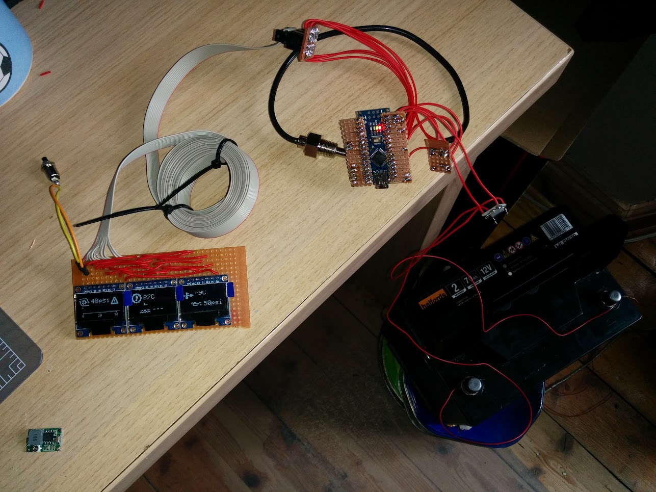
Convert from breadboard to solder & strip board
Package it all up into a little project box

Thought some people might find it interesting, or not :D
 
Last edited:
You're a bit ahead of me, I have an Arduino mega 2560 on order along with two 16 channel servo boards , and the first 10 servos of 100 are on order for a model railway Project. But I have already been considering a dashboard for the 110.
I did consider using a android tablet to control the Arduino, and building a star trek dashboard but that is more out of place and I happen like the look of traditional instruments. I have a bunch of them left over from years ago that are not necessarily compatible. But a servo could be mounted inside and by the time I've finished the previous project I will have experience of them!!
Alternatively I might make a row of mini servo gauges as I could get more in that way. 9 gram Servos are 99p each from China in packs of ten so you could get a row of 10 mini servo gauges in maybe 12 inches by 1.5 inches of dashboard.
When you're driving, reading a number from a set of numbers can be difficult but you get used to seeing when a dial is in the green and notice when it's in the red.
As I drive a 110 I don't know what instruments you have in a D2 as standard, but I'm intending to add to your list, a rev counter, voltage monitoring, possibly current as well, outside air temp so you know if your likely to find ice, inside air temp 'cos if you've done one the other is easy .
If I go this far I may remove the current dashboard entirely, put the current speedo inside the cubby box to keep it legal. And then replace the dashboard entirely with GPS module, engine temp, all the stuff mentioned before and even the clock being Arduino powered

I've also been looking at a separate arduino security system, removing the starting electrics from the ignition switch and fitting a numeric keyboard shield. So you just type in to unlock the systems and then button press for ignition. Alarms that go off if you don't unlock the system within so many seconds of door opening or if the vehicle is moved . It would also be possible to go keyless entry and have an RFID credit card you just wave at a pad near a window or come to that I've seen a finger print reader available somewhere.!
 
Yeah the possibilities are endless. The Mega's have a lot more scope with the extra digital io and analogue io. I just want a few extra simple guages... I'm sort of liking the outside air temp idea thoug :D
 
You chaps may well be able to guide me, so sorry for a) thread drift, and b) being completely unable to chip in with helpful comments.

I've had a pc running Windows built into several cars over the years, but would like to go a step further than I have previously and have an lcd display showing 'instruments' on the screen (speed, rpm etc). I'm assuming that I need some external box(es) which via usb/serial convert dc levels or pulses into digital stuff, but it's what I need by way of a gui etc that I'm clueless on. I have a windows 'phone and some of the graphical clocks available as apps are absolutely stunning, and was thinking of writing to the seller/designer and asking for his help with the graphical end of my problem, but would need to tell them how and what type of input they'd be working with.
 
Since people often use a PC to programme the Arduino via a USB, I think it would comparatively easy to use an Arduino as your sensor controller. That would pass the info on to your PC for display. I suggest you do a web search on Arduino projects particularly vehicle ones. I think with what youve already done you'd be able to cope with Arduino programming and sensors
 
OK so got thermistor input working, some maths that was a bit head bending!

Also fixed the gauge display so it handles negative values properly AND added a peak value indicator.

 
Last edited:
Bit more progress...

Peak values are written on the gauges scale....

High and low warning values can be declared for each sensor, and an animated warning triangle displays if those limits are exceeded.

 
Despite being full of flu I managed to get the displays off the breadboard and soldered onto the remote daughter board.

Using 2m of 10 way ribbon hooked up with an IDC connector - will probably make the Arduino end a bit tider/more secure once I get this into it's case.

mso0K-RWWsnceSt26VZBnhH7YdV0B0yhS1Fn1G1f-0P0mYaC5hPG8wATuvLuQpM8opAVs1_RDXmyATLmTmWSX19oeTTek8aEjGe7mLpImAhhqYzGWrD2bx-Onje2ji5LWuXKFTqnSqQ_bheW6zJGjfbGj5PGKiuFjb339PHmrhmwmqoK86WV7u23CRDwopdl1yGbABv-MK1fWXrZ-WkKkh-hWnVJfr1FT4A0Zw38TD0LRp8Zy_TEoD2BsFucidO5AerLCWlOKILWWiS3Hq6YUVjFpORspL_U_xhUi7B35rhaK5ocwX99i-bqsV4HpsbQMv_u6wUEckmg1NvT8CcnWNdoSmBElVKWGvxhePSgM0WhO67aJy2flBQ0YsvNZxDfv1sE5kArCVEGU7-pSlBvW5EiSHqZcN1wvRsGl4nHTLUyd-lEydINAGK3jTmAx51-fgFY5BecAlezOULV9D4b4Io1ZrLkokwn_y3-TroHID8KzSNLM4wNdPQyrdHUcpEVgmfpbk56MkhD5DIRRdVkAB3t1cPC2AN8Ucji4Rnp-38s12MsVnOjgGVCqTeLopXWMfk0=w1287-h965-no
 
That looks really good, the graphics look really professional

I also kind of did an android controlled system using an arduino and a bank of relays. The idea was to be able to turn various spotlights on and off over bluetooth via the app and also have some gauges on the android tablet.

I got it about 50% done but gave up on the android side. This kind of makes me want to finish it, though its uses are a bit limited for what I have.
 
Yeah I thought about hooking it up to my android phone via BT but then the problem is startup times, not being able to see stuff when using satnav etc.

I've got it all transferred onto the nano now. Just waiting on terminal connectors & the dc-dc buck converter then it can go in the car.
 
bubk-buck converters and the terminal blocks arrived.

first converter didn't work, which is a bit of a pain but the 2nd one was fine...

Hooked up to a car battery with output voltage set to 9v:

BeXAUURYj39u-w0OvX9SkEDvy1Vm0TW5wI8HPzDt2Ddjw3CSq742ISHzPOlnCVRPl-lWuHTzZK4NXVjR7UpO9NBXX7-VHnEPcg1Zfxibw8Q7TyfpNnaVdVARCZ0cxklH9HKxR93vajcGw1q_KNaWwjFBhvJ62U7ItMg2g_R_WZ6BRhZNpFUZ-_fKt8znLfPu-6ZQrxAi1FwM7xcyLlWsgfeD-Ex8rrPppXRMiwIE4Kj3a5jT75sqN867YNyQAzqvoHEUCnA0gTQ5oWaJK-3bk69SDRgB9_W_t3z-gjd7qVXlEwyE5YnnAwgvBK2pj9yl6y5IoAuO3Fg1qGB9U_6_4l1zBXgOHPudf72R3BFJdY1o5I7YJy9q_qZR464FBE2LYpu68ip3SNVDTssPL6e1oswaSVPDpOOPxYDbYkY7juD5QqovKt9K-8999zMJ27CSarhchPiI-q2ENFWMibMmkxvU8Bxq4c8IiINlHJ7HqBN_1wzLOu4NGVlZ2RPsp7mG_C_hQP8S1c6RxWWmgiUn7iAJbtkdOmGoa9rFqRCWB8cM94Ao_41EgFSb5hT6NxiAhzpR=w1287-h965-no
 
And it's in the car... need to wire up some more of the sensors but the boost gauge is working nicely.

Crap photo but you get the idea - so much easier to read these than the old LCD...

Xsk66h5cirfkXjZ9PWj8YsjLQ02Ly1x2s02wHp8jIZl-DZuC6OVovMUTgOhDw9OTS6jWuAKG9hC_-cGxx7W2vDWfizDFXDvbO-bowQpjcOwm03if_YO_ftJ5qqcgiyJDsGv0q31cLNc_H4A-D98UZFnYoQd6YTIg_3DiNNQKZZ_3logZZQ9WBdCMx5SbbmX55Kkr2PFQA-LdeFJZ29h2Re_b_ExwqZdK44A1h3LlDmcZdnpcgJyXXkJZm7lW4peCUxstNsRHbxNVL5Xz_J39jXvTjfWZMXCHukAx6ffAZPCTTiJFTkvc3N-flXgyCrbEyNCEJzTpTnocQiPUeZQK7UsOqujOQu9dF0nfBJhe7a0k2RjVtrXvjODOgmaJtn42GK7WYQsMxXhj00qdVfmn0sBx5XWSi5QVPzEK-BpG8TGHM4vGMKw6nDNBEhd1v19jYBXQim9ubq9gbFurh6_El_2-3170sFnwP5SghUbCx36daLJrU1CziqUqbO8xUX36z4wojHoPAvSC5XdABiZ1WUovYGSZso1VjBfLPV01exxbBFQx9LnEGY_I2-eROj_QU7P6=w1287-h965-no
 
Got a MAX31856 thermocouple IC a while back before getting sidetracked on the axles

Anyhow, soldered it onto one of these

TSSOP14 adapter arrived, it's bleeding tiny...

3lcrdzYjJM5u_WCuZ0J71ve8klXSghgWvBiWkBrxG13_F_PCX-T3_yHxiGJVNJ__t7UdCvDKQQYvoIv-RrgEP1EZqSHBogdPVxDJiGKHy91Uv35B5bxOhD93-rBGhA_xXkOAzJbEdnHjVRKLf06dbduqNaOxg233KZT0YIhc-8NzHRFPnuKvDyXQJjbh57HNlf8mdXQ5irnlLbmiNoz3Q5jFIgaISt4htYsR153xGtaENxKqIk-Gq6gyvdRfUA_CnaDxupEOdhemRm8bCLeuoWNPV34hyXpOtKlUujRk7HoMAF0foFaMEAy08Wd3iRnAmfrYuTQuNj7wTynHo1yHhkiK7YdaVae_jG1CZkDy_AOIJ22tChwA1gvh07-Du9bopY9ue_NYicJK5nKaebk_kTTjO0-RF9Hx-FDDJTPsDGyt79wpSYReuQ9LCanIK5SuorGhg8heoqLc35nm31xFr2wWH_Cdkb_Gz0RbI1qTiEekNyizyb-vAQZzo0OFi73EP4g2TRA-7Ytn_SqwtYUTUiFGAurDjCrHlUQ42Mf3dNCjjNGUGX-veRHRfomVa51WiwHT=w1228-h921-no


I've had the datasheet out for the MAX and I need some 0.1 & 0.01uf capacitors to wire it up properly, not got any in the spares box so I've ordered a 1000pc assortment from ebay for a fiver.

Tidied up the fascia so the multigauge looks nice in car:

okflhQQmI1SnzdgZgiT16o-Th8WTQHzjrIiZl1JVFquZgjHg0_kX6gAWRUZRwHrcUTwUBHKLe4Zo4SAeg6XDZuzRMYEiKnfZbzSx5Qz-42EMYuJcau6H_nGYpzpDycGeHtQXpX8yDL1_fXW4TrY4-JRYPw9uyRQguvESDNByzTwqGtRVXD0B8ujRVxBAs_ZeuaPb4CoCQV_M2ahYmHnNFc2ju4a3GqQ2B5Wr8VobsKyawLrXZIAjanlzvnSSXS-ujYHy1m2cUtUuRbW9NC5koN49KFE6uxzfaSbk4WNa9F_iyn55DQZ1f97HTbhfAor73FXtt1wISLvPDftEFsoRDw9vD0DfXvfcdMq8cgjpzXQVpc_Sgghs0GIRvYHRFEiQTBH88KJESEuk1zDQT9G2FWsTv91XMHzVpHjGXZyFN1g8nb5voZXkBKhkMuULPvQTIHLVpw6as9ZR-SFC5pee4IY_5WWq3UyAVhJP9JKzrkmJKhWb4Y3FQgJrW7R9rL8VOMCWcMimtGMx1hDWDPnkLwQMLvJGXkA6E6e2zQlx-32uQU-v3yq4Dn8X0FlXqGXieBWAfpYTENmYKqT7qm3hm6Ve4eao7Ak=w1287-h965-no


Nice thing about this sensor is there's no frigging about to do in software to convert the readings, it also has a cold junction sensor embedded which means that I can get the approximate ambient temp to display as the 'outside or cab temp' - so I'll probably swap one of the sensor display values over to that.

Also ordered a replacement boost sensor which looks less fragile than the old one and also has a nice connector making for an easy disconnect, useful whilst debugging.

I'm going to change the transfer oil before heading off to France this summer so I'll be fitting a t-box temp sensor at that point too and wiring it back.

Allisport exhaust manifold is also coming off due to a minor warp so I may get the turbo housing tapped for the thermocouple at that point.
 
Last edited:
another warped manifold! That's a bit crap... How many is that now?

This is the 2nd - technically 3rd if we include the stainless steel one that I managed to snap in two.

The manifold is a cast allisport one too, to be fair they've been brilliant customer service wise.
 
Great little project you've got there, wish I knew enough about electrics to do bits like this
 
Back
Top