Hi folks,
As the header says.
I have a 2 speed blower motor with one spade terminal and one earth lead coming out.
I did not take it off so I am not 100 pc how it connects back.
I connected both wires from the bulkhead to the spade and it works only at one speed. Swapping the wires around connecting one at a time. gives me the same speed from both switch positions.
From reading here and online I am assuming there is a resistor inside the motor housing?
Has any one a photo of the inside of the fan or any further guidance .
thanks peter.
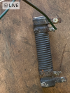
After having a rummage in the garage I found a resistor and other odds and ends in an old cardboard box. I must find the correct way to fit it now.
Attachments
Screenshot 2023-08-02 at 17-17-47 iCloud Photos.png
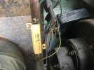
The resistor should be on the bulkhead or near the heater radiator , the fan has the one connection , the 2 speeds come from switching the live either direct 12 volts or through the resistor getting a lower voltage which makes fan run slower, you prob don’t need the 2 speeds as it don’t blow much anyway
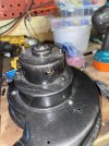
I have found a picture of the arrangement online, interesting. The fan was already removed when I took over the build.
I just cleaned and painted it, there was no resistor there.
I had to rebuild the heater matrix box,it was rotton although the radiator was fine.
Any idea of the value (ohms) of the resisitor?
cheers Peter.
4.7ohms but the 50 watt important too , other way round on mine heater box good the snail casing poor
got mine from electronics shop rather than online
The resistor is fitted inside the blower snail housing. It heats up when the low speed setting is used, the fan draws air over it for cooling.
The two holes shown in your photo of the housing are for the rivets to hold the resistor in place.
I bought a new replacement resistor back around 2014 when I rebuilt my Series 3. I am not sure if they are still available.
The circuit diagram in the repair manual doesn't show the heater wiring. However there is a section on how to remove the blower.
There should be two connectors on the engine bay wiring loom that connect to the resistor. One should brown/green. This connects to a green/grey wire running to the blower resistor. The other is green/yellow which connects to green/yellow at the resistor.
The half speed wire runs the current through the resistor coil and to the spade terminal on the motor. The other is still connected to the resistor body but bypasses the coil and feeds the same wire to the one spade terminal on the motor.
The motor is earthed through the black wire to the nearest suitable bolt on the body using a ring terminal.
The manual doesn't say which of these wires is for half fan speed and which for full. Tracing the wires back to the fan switch would probably show it.
Here at LandyZone we have plenty of very knowledgable members so if you have any questions about your Land Rover or just want to connect with other Landy owners, you're in the right place.