Glow Plug question for early model Series 2A Diesel

This site contains affiliate links for which LandyZone may be compensated if you make a purchase.

Guidoma

Member
Posts
36
Hello all

I am seeking some advice regarding the glow plugs and wiring on a 2A series 109 Land Rover with a 2.25 diesel engine I am slowly restoring.
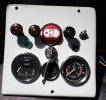
The vehicle has the original ignition/light switch combination in the centre of the dash, with the keyed engine start ignition switch beneath the dash beside the engine stop knob.

Unfortunately the ignition switch beneath the dash was damaged in the past and at the mechanism doesn't work at all. The vehicle was converted to alternator and negative earth at some stage.

To start the vehicle we hot wire the glow plugs with a heavy lead from the positive terminal of the battery to the ignition switch side of the glow plug resistor, allowing current to flow through the resistor to the glow plugs. We do this twice to ensure the plugs are heated and then get into the Landy and turn the centre dash ignition key to crank the vehicle over. This usually works.

I have a replacement ignition switch which has the Off, Glow, Ignition and Start positions. The switch is not rated for the heavy draw required and is and needs to be wired through a relay to control the current to the glow plug and starter.

My question is what size cable should I run from the battery to the relay (fused) and relay size for the glow plug circuit? I intend using the original series type glow plugs as the set on the motor appear to be quite good still and I have a friend who will give me another unused set of original type glow plugs at a very cheap price if I want them.

As for the relay size, some people I have spoken to say a 50 amp relay would be the absolute minimum for the glow plug circuit, while others say 30amps is ample. I am very confused about the correct size.

Also, the glow plug light isn't functioning. I took the amber light out of the dash and found the bulb holder was corroded solid and the bulb is stuck in in. I will be replacing the globe holder with a replacement wedge type holder, but is the bulb for the glow plug light meant to be 6 volt or 12 volt.

Any advice would be greatly appreciated.

Thanks

Guidoma
 
What type of glowplugs?
Early ones are pigtailed and later one straight
Pit tail type not 12 volt, cant remember what volts they are! They also have a resistor on the bulkhead which glows ref hot when in use
Straight ones 12 volt

Wire size I would say 4 to 6mm section (not diameter) and the bigger relay would be the way to go.
 
Hello Lynall

Thank you for your reply.

The glow plugs are the pigtail type glow plugs wired in series, with the lead from the last glow plug going to earth on the chassis. There is a resistor on the bulkhead.

What confuses me even more is the glass type fuses in the fuse holder on the bulkhead are rated 35amps from what I can see.

The vehicle is a 63-64 Series 2A 109 utility (pickup) which at some point was converted to a delivery van by a local Australian company who specialised in such conversions. This was done probably in the mid to late 1960's as two extra headlights were added to the front of the vehicle on the wings but were not recessed into the wings as per the late series 2As and Series 3. So it has 4 headlights in all, 2 on the radiator panel and two on the wings.
 
I dont think the pig tail type are fused at all, certainly my 59 has one single glass fuse, same as yours rated at 35 amps, and Iirc that is s for the horn and wipers, the rest of the system is unfused.
If you have been putting 12v to the plugs themselves you may have buggered them.

The system is strange as you apply 12 volts to the resistor it applies a lower voltage to the glow plugs and the warning light comes on, and as the glow plus get hotter the resistors resistance changes and the warning bulb glows brighter, I think the bulb is also not 12 volt.

The glow and starter circuits should run from a tractor style ignition switch located under the dash next to the engine stop cable, the tractor style ign switch can handle the glow plugs current, so no need for a relay.

So you have two ign keys, the normal one for ign lights/gauges etc, and the tractor one for glow and start funtions.
 
Edit just checked the manual and I lied! the glow plugs do get a 12v supply from the resistor, but I think they are wired in series like christmas lights of old so one duff plug means none of them work, this also means the plugs the plugs themselves are not 12v each, plus I am sure the warning bulb is not 12 volt

Old thread with more info and how to convert to later style plugs and the wireng etc.

@steve2286w still posts on here so might be worth pinging him a message.
 
I dont think the pig tail type are fused at all, certainly my 59 has one single glass fuse, same as yours rated at 35 amps, and Iirc that is s for the horn and wipers, the rest of the system is unfused.
If you have been putting 12v to the plugs themselves you may have buggered them.

The system is strange as you apply 12 volts to the resistor it applies a lower voltage to the glow plugs and the warning light comes on, and as the glow plus get hotter the resistors resistance changes and the warning bulb glows brighter, I think the bulb is also not 12 volt.

The glow and starter circuits should run from a tractor style ignition switch located under the dash next to the engine stop cable, the tractor style ign switch can handle the glow plugs current, so no need for a relay.

So you have two ign keys, the normal one for ign lights/gauges etc, and the tractor one for glow and start funtions.
Thanks Pal

What we have been doing is running 12 volts from the ignition post side of the resistor, so current flows through the resistor, then through to the glow plugs as it would have done if it was flowing direct from the ignition switch itself through the resistor.

My replacement switch however is not a heavy rated tractor switch. The terminals are only rated at 15 amps, hence the need to include a relay in the circuit.
 
That should read we are connecting current to the ignition switch post side of the resistor, so it flows through the resistor and then to the glow plugs, just as it would if it were operated by the ignition switch.
 
Anyway mate

Thank you for your advice. I think I will consult with any auto electrician next time I am in the big smoke and purchase a couple of metres of decent sized cable as well as the appropriate sized relay.

I am off to bed now, it is 10.40pm here in Western Australia and I have work in the morning.
 
may help assuming it a 16ACR you fitted
 

Attachments

  • alternator_Land-Rover_2-2A- - Copy.png
    alternator_Land-Rover_2-2A- - Copy.png
    135.8 KB · Views: 85
  • alternator_Land-Rover_2-2A- 2.png
    alternator_Land-Rover_2-2A- 2.png
    144.6 KB · Views: 74
Last edited:
Thank you so much for your advice chaps.

I did a quick run into the big smoke and stopped in at a couple of auto electrical businesses. Both had a look at the replacement ignition switch I had and also your diagram, Mystery. I ended up collecting a Bosch heavy duty relay and some 6mm2 cable to supply power from the battery to the relay and relay to the glow plug resistor. I will put an in line Maxi fuse between the battery and the relay and work out where I will get the trigger supply from for the relay when I clean up the old wiring.

Thanks again
Guidoma
Disregard the last sentence of my post, after "between the battery and the relay". It has been a long day.
 
I just converted my '64 SWB from pig tail to straight heater plugs. Mine not an original diesel so can't comment on originality.
12v supply goes to 70 Amp relay through 20 A rated wire. Relay is switched from the standard ignition switch. There was no light, just a relay click to listen to. On changing I fitted a 12v 'peanut' style bulb fed from the now otherwise redundant resistor.
With the original plugs you will have 12v from the resistor, which will be down to about 9 on the last plug.
If you do change, remove the final earth from the series.
Thanks for that Shedload. Good to know. I have a 70amp relay and 50amp rated cable. Point of interest, you say a relay click to listen to. Where did you mount the relay, within the cab or on the engine bay side of the bulkhead?
 
on my 1957 series 1 the glow plug have been replaced with 12 volt type ,resistor removed and the relay is mounted on the bulkhead behind the speedo panel with cable from relay coil supply to the warning light ,safe from water ingress and protected by a 50amp maxi fuse on inner wing panel just after the battery .bearing in mind it's not a rivet counters delight and is being rewired with relays ,20way fuse box and a main isolator switch to isolate the battery supply
 

Attachments

  • ampmeter and glowplug supply fuses.JPG
    ampmeter and glowplug supply fuses.JPG
    152.6 KB · Views: 72
  • 20220803_104850.jpg
    20220803_104850.jpg
    267.1 KB · Views: 64
  • 20221118_121140.jpg
    20221118_121140.jpg
    240.3 KB · Views: 73
  • 20220822_100515.jpg
    20220822_100515.jpg
    255.9 KB · Views: 81
on my 1957 series 1 the glow plug have been replaced with 12 volt type ,resistor removed and the relay is mounted on the bulkhead behind the speedo panel with cable from relay coil supply to the warning light ,safe from water ingress and protected by a 50amp maxi fuse on inner wing panel just after the battery .bearing in mind it's not a rivet counters delight and is being rewired with relays ,20way fuse box and a main isolator switch to isolate the battery supply
That's great Pal. Thanks for that - another idea to write up in my notes. Really appreciate that.

Guidoma.
 
Back
Top