You are using an out of date browser. It may not display this or other websites correctly.
You should upgrade or use an alternative browser.
You should upgrade or use an alternative browser.
Electronics help
- Thread starter leezg
- Start date
This site contains affiliate links for which LandyZone may be compensated if you make a purchase.

A better photo of the new part would help.
Looks like it's switching a relay....so there really should be four connections...
However, if there is only three it would suggest there's going to be a common earth, then power for the relay and then the power thats going to the compressor (or maybe power to the relay that controls the compressor?)


discomania
Well-Known Member
- Posts
- 6,949
Hi all, I am a electronics noob.
I am trying to change the switch for my compressor in my defender to a remote control switch. The old one is the one on the right.
How do I connect the wires?
I only have 2 wires, + & -

Being a remote switch it will need it's own power supply, so, I would expect it will have a negative, a live in and a switched live out.
Negative is so it can run itself and the live in will be for running it's own electronics and to then switch out to the winch relay.
This is just based on what I can see, and my understanding of Chinese! So if you blow it up don't blame me.
The close up of the 3 connections suggests a switch symbol on the 2 on the RHS of the close up, so these are the lives - I would personally connect the one on the right to the live, I would then connect the one on the far left to the negative and try your button, I think it will click away.
If you had a meter you could do a continuity test between the LHS and RHS terminals, I think you will have continuity there as that is via the switch electrics, you should have open circuit between the two RHS terminals with the switch off and open circuit between middle and LHS terminals again with switch off. If this is the case that confirms what I have said above.
Also, look on the relay, you will be able to work out which pins are the switched and probably follow them out on the PCB, you will also be able to see that the RHS terminal probably goes into the relay and then has a track which takes it to the switch electrics.
Unless it is negative switching then all of above is the opposite, but I doubt it.
Have you a link to the manufacturers website, or sellers site?

I connected it as shown on the photo and nothing.
I have a red + wire and a black - wire. When I connect them directly the compressor turns on.
Try adding power to the vin and ground to gnd - try pressing the control and see if you can hear the relay click
discomania
Well-Known Member
- Posts
- 6,949
It is not for a winch but a 12v air compressor.
so something like this?
Sorry, misread it, same wiring anyway just different load.
I think I know what you are doing and it won't work like that.
You need to connect the far left to negative, not via the compressor, that is not a negative, that is the switched supply out to the compressor if when you touch them together it runs.
Tread carefully here, I know what you need to do, but if your not certain what is what we could cause damage to the switch here.
Forget about everything else just now and think of it as a electronic device rather than a switch.
You need to give the device a supply, so far left goes to negative, so a good negative somewhere, or the chassis bodywork. The RHS needs a live supply, the compressor live should do as I suspect it will be upstream of any compressor electrics, then connect the black wire which goes back to the compressor to the middle terminal.
So basically, leave it sort of as it is, but take the black wire out the LHS terminal and replace it with a negative wire.
Then try the remote button, if it clicks, connect in the return wire to the compressor into the middle.
Can I ask, was that switch originally on the body of the compressor?
skint-as-usual
Not a well Known Member - with no likes
- Posts
- 2,411
- Location
- County Durham
Hi all, I am a electronics noob.
I am trying to change the switch for my compressor in my defender to a remote control switch. The old one is the one on the right.
How do I connect the wires?
I only have 2 wires, + & -
http://s144.photobucket.com/user/elpresidente_zg/media/Mobile Uploads/20150422_085129.jpg.html
Look at the printed circuit board:
It has a 2 pin power connector (marked + and Gnd). There are common connectors, usually 25thou (inches) square on a 0.1 inch pitch. You can probably get one from maplins - may be crimped or soldered.
So that will get power to the IR receiver and the relay.
The relay has the 3 way high power connector block in blue.
This is because it is a SPCO relay. Single pole change over.
The printed circuit board shows the NC, common and NO contacts.
So it is up to you to feed (probably a fused) power to the common.
Then a cable from the NO contact to the compressor, then an earth (ground) from the compressor.
Check it all with a meter too.
And the IR Receiver needs to be somewhere sensible
")
discomania
Well-Known Member
- Posts
- 6,949
Wait a min...
Last edited:
discomania
Well-Known Member
- Posts
- 6,949
OK, I'd not looked at those pins at the back before, so try it like this:

So basically your relay replaces the switch. It looks like it is always closed circuit via the two outer terminals, so use the middle and LHS as they will be the normally open.
If that makes the compressor run continuously then swap the middle wire into the outer position.
So basically your relay replaces the switch. It looks like it is always closed circuit via the two outer terminals, so use the middle and LHS as they will be the normally open.
If that makes the compressor run continuously then swap the middle wire into the outer position.
Last edited:
skint-as-usual
Not a well Known Member - with no likes
- Posts
- 2,411
- Location
- County Durham
OK, I'd not looked at those pins at the back before, so try it like this.
My thoughts were as follows:
Attachments
discomania
Well-Known Member
- Posts
- 6,949
My thoughts were as follows:
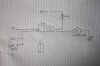
Same circuit except your circuit assumes the original switch was remote to the compressor, my circuit assumes the switch used to be ON the compressor which the OP also said it was - like the 'assumption' sketch - which is how I think the wiring inside the compressor works, minus pressure sensor, overheat sensor etc. if fitted.
discomania
Well-Known Member
- Posts
- 6,949
This thread has got me thinking, I think I will fit one of these into my land rover to let me remotely control beacons.
Where did you get this one?
Where did you get this one?
discomania
Well-Known Member
- Posts
- 6,949
Discomania, I got it of ebay, just search 12v remote switch.
So I connect the other side to the car battery + and 0v ground it to the chassis?
Yes.
Go get a piece of wire and try temporarily connecting it to see if it will click away on the remote.
Can you solder? One option would be to solder the wires onto the pins and use a little heat-shrink to save having to buy a plug.
By the way, how many amps is your compressor?
I see 4 channel version! I could have my lights and other stuff on it - does the wee remote seem robust enough?
skint-as-usual
Not a well Known Member - with no likes
- Posts
- 2,411
- Location
- County Durham
Discomania, I got it of ebay, just search 12v remote switch.
So I connect the other side to the car battery + and 0v ground it to the chassis?
The 12v to the IR receiver and low power relay side I would recommend tying into IGN switched electrics (such that it is not on all of the time).
These may be white IGN unfused
or
Green, from a fuse (say fuel gauge?)
Similar threads
- Replies
- 14
- Views
- 2K
- Replies
- 2
- Views
- 479