tyregeezer
Well-Known Member
- Posts
- 540
- Location
- Rural Norfolk
Will pull out the liner tomorrow check out the wiring too will run through it piece by piece
Will pull out the liner tomorrow check out the wiring too will run through it piece by piece
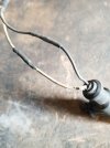
Sometimes eyes are better than a meter!Found this r/h speed sensor no ohms bare wire and a join hopefully this is it l/h to check
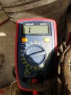
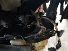
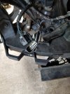
Run through all plugs today cleaned with electrical cleaner nothing untoward. Used cleaner on the outside of the plugs to help to free off the little clips. Visibly all looked ok, checked out speed sensors as this could explain at least two of the codes I think, one was faulty and damaged but later on found I could get intermittent reading, ordered two new sensors for the front and also a brake sensor, couldn't unplug the rear valve block without removing it so will wait for new one as I want to check other issues. Fitted another oem front valve block hopefully will take care of one code.Tomorrow going to try to check continuity from the dynamics unit to the sensors when I've worked out how, I suppose worst case scenario is dynamics unit to ecutesting.com, ironically found more issues bottom arm and brake pipe on l/h will keep investigating, other stuff to do tomorrow but back on it in the evening
Welcome To LandyZone, the Land Rover Forums!
Here at LandyZone we have plenty of very knowledgable members so if you have any questions about your Land Rover or just want to connect with other Landy owners, you're in the right place.
Registering is free and easy just click here, we hope to see you on the forums soon!