Freelander Project IV (Bertie)

This site contains affiliate links for which LandyZone may be compensated if you make a purchase.
Here ya go @Alibro
Just got the gas axe out and shifted the rear wheel for ya :) .....
Just need some tweaks to the arches now :)

225 75 16 ali shifted.jpg
 
Good point Grumpy!
Sorry Joe no time to read your response this morning but will do later however my gut reaction is it shouldn't be much worse in full compression than it is on full droop so I could go half way from where it is now to the centre point and it would be approx OK but will probably go the whole hog so it looks right when on level ground and see how it goes.
With the trailing already at an angle close to 30 or 40 deg I guess the maths would be further complicated (not sure if you took that into account Joe) and the wheel would move a different amount on compression compared to droop.
Any suspension changes will cause issues which need resolved but that is part of the fun.
 
I see lots of text and some numbers - but a few pints of Twisted Hop Challenger (a rather nice beverage) wins - I shall read in the morning to see if you think I was being a **** or making sense.
 
YOU KEEP YER GRUBBY MITS ORF MY MOTOR YA BIG BALIX!
Nope - chopped yer arches too and tee cut the bl00dy thing ya idle beggar :p

And yes in the lonnngggggg suspension post - I took all the relevant suspension factors into account :)

225 75 16 ali shifted rear front arch shiny.jpg


You just need bigger wheels now :rolleyes:
 
Last edited:
Edit - this started as a quick response .. :rolleyes: - but... forgive any math errors or otherwise.. it is early and I have been up since 5 AM..... if any of my angles are t!ts up then please let me know..:)

Hi GG, you are absolutely correct and of course the amount of movement is related to the increased angles. If you take - for example - a hypothetical 500mm trailing arm at horizontal with a pivot point at one end - (x), call the 'movable' end (y) then if you 'drop' (y) 50mm from the horizontal the movement in the longitudinal axis is less than 3mm. - however, if you drop it 200mm then the longitudinal 'shift' is around 39mm.
LR originally set the suspension so that the trailing arm was inclined downwards when normally laden so that the wheel moves 'backwards' as bump increases. max drop angle (down from horizontal) was always greater than the max bump angle (up from horizontal) .. so as we approach high defections upwards there is a virtually null area.
ie, - from 5 degrees 'down' from horizontal to 5 degrees 'up' - the longitudinal shift is only +/- 2.5mm. if the arm is set - at normal laden conditions - at, say, an angle of 15 degrees 'down' then for the first 10 degrees of movement (which is a 'bump' of about 100mm) the shift is around 20mm to the rear. As above though, once it approaches and passes horizontal -5 to +5 degrees the shift is only +/- 2.5mm.
Herein lies the problem with 'lift kits' if you do not alter the suspension arm fixed pivot points at the same time. :(
All you can do (if you are not prepared to alter the fixed points) is to find a compromise so that the wheel 'looks' ok and remains clear of the arches through the range of travel. The issue with the rear wheel being close to the forward arch is that as 'drop' increases - which it certainly will off road! - then the wheel will move forward at a much greater rate. The shift from a static angle of - 10 to -15 is a movement of 12 mm towards the arch, however, from 15 to 20 is a further 16mm.and from 20 to 25 is another 30mm !!!!
So with a horizontal arm of 500 mm at 0 degree drop there is no deflection of course, but the FORWARD movement of the end of the arm (y) from the horizontal / 0 degrees are approximately -

5 degrees = 2.5mm
10 degrees = 10mm
15 degrees = 22mm
20 degrees = 37mm
25 degrees = 70mm !!!!

extremely non linear as would be expected. - and that equates to a downward movement from the horizontal of around 250 mm.
Whether this amount of drop is actually achievable (FROM THE HORIZONTAL ARM ANGLE) with the FL suspension when the 50mm lift is added I do not know - It would be useful to know the full range of a normal setup suspension travel from full bump to full drop - but shows the huge increases in wheel shift as the angle increases. As the kit has increased the downward angle of the lower arm we can see the results on the wheel movement already in the images, and this will only increase at a non linear rate as the wheel drops

So - by fitting a lifting kit (at the rear)we hit two issues - well FOUR actually....
First is that the trailing arm is deflected down at a greater angle than design leading to the issues above - a MUCH greater amount of longitudinal wheel movement in drop or bump.
Also, if the angle of the trailing arm is increased downwards at rest - as it is due to the lift, then the position of the wheel will move rearward as the bump increases FAR more than was originally designed. A wheel set at arch centre on a raised kit may well move backward up to 70 mm depending on the length of the arm - and that is only to the pint of the arm being horizontal !. the 70mm is for a 500mm arm at 25 degrees down from horizontal (at rest) - greater angles will cause greater shift.
The wheel could well hit the REAR of the arch under bump.
The 'sweet spot' that the manufacturer builds in - ie the point where under normal expected high bump the arm effectively pivots around horizontal giving minimal movement after the initial rear shift is lost as the vast majority of the travel is below horizontal.
The camber is positively increased far more than standard when static and is only exacerbated under droop / drop
The toe in is increased far more than than standard when static and is only exacerbated under droop / drop
So, it ends up a real hotch potch to say the least.
All that can be done really is to get the wheel in a position where it clears everything through the full travel range and also where possible is aesthetically pleasing.
Increasing the trailing arm length is actually beneficial as it reduces the rearward deflection on bump..
A 500 mm arm would show a horizontal deflection of around 70 mm at 25 degrees whereas a 530mm arm would only deflect 56mm at 25 degrees and the added bonus is that for the same drop the angle is reduced with the longer arm.
It is a can of worms really.
The rear can cause some quite unpredictable handling on road. - to say the least.

The front though ... is a complete new ball game.
The freelander though is not a sports car, however, at the front the biggest concerns would be caster shift, camber, tracking and bump steer all of which are potentially dangerous - some alarmingly so.
Then there are the deflection changes - the above potential 'issues' for the front are merely presuming the differences from 'normal' remain STATIC - they dont - they always shift with movement but the manufacturer allows for this. By making a considerable change this all goes t!ts up - and what is 'not too much of a concern' when static can become 'yikes - adrenaline is brown' when travel shift is taken into account. (it really can be very dangerous). One would presume that the manufacturer of the 'kit' would have done all the tests and measurements and provide all the info you needed to know and appropriate advise / warnings - apologies DD - if you do this already - .. :( - at the very least - if the kit has not been properly assessed for changes and potentially dangerous issues, then a warning that 'it has not and you fit it completely at your own risk' should be included to warn the user and cover the seller.

What you would normally do is assemble the system without the springs and measure the important angles at full drop and full bump. .. it is a veritable minefield.

Joe
As lift kits have been sold for years and many folk here have them without complaint I'm not overly concerned about the potential issues.
If the car was my daily driver I might be a bit more careful about it but so long as it isn't dangerous to drive I'm happy to go ahead. I suspect this car handling badly will still be significantly better than the average Disco 1 or Trattor.
As I said earlier I'll take a few measurements, look at the angles and decide how much to lengthen the arms by, but I'll probably extend them enough to put the wheel in the middle of the arch when on flat level ground and see how it goes. The Tyres are not that big to be a major problem and I can always make minor adjustments to the arches if need be.
No worries Ali, whatever works for you.
I would be surprised if there were many 50 mm lift kits in use ? - but hey - possibly there are.
I was merely attempting to indicate that if you put the wheel in the middle on level ground you could end up with a considerable rearward movement on bump. It all depends on the angle the tie rod is at now. The (apx)70 mm rearward movement is what you would have with on an arm length of 500 mm and a level ground trailing arm angle of 30 degrees. With the suspension then compressed to bring the tie-rod to the horizontal position the wheel will have moved rearwards by (apx)70mm.
If the angle on level ground is 25 degress then the rearward movement of the wheel will be around 50mm (based on a 500mm tierod)
I think you will find the angles for the tie-rod are probably much less so it shouldn't be too bad. It will be interesting to see the results.

Oh btw, did you get the spacer ? and if so, what do you think of them ?
Joe
 
I agree Joe and intend to do some checking and measuring before making any final decisions but I'm hoping the rearward movement on compression will not be enough to cause a problem. I got them from DD at a very reasonable price and they look very well made.
At the minute I'm more concerned that Eurocarparts are messing me about with the parts. I knew they weren't in stock when I ordered them but got an email saying they're checking availability and price.
Ah ! - so you got the DD Spacers ? -- excellent - they look spot on. I actually ordered some the other day - paid by PP I thought they were damn good value !!- but - unfortunately the checkout didn't add the darn shipping. ...... When DD checked to send them out, he noticed the shipping wasn't added. Unfortunately it was going to cost nearly as much as the spacer to send them here... :(
I will try the ebay ones as they are so cheap - I can throw them away if they are cr&p... otherwise I will get the local machine shop to lob the end of the old discs...
Laser cut items like DD Spacers are simply awesome. I think he is going to add lightening holes to then on the next batch to reduce shipping costs.
It's can be beggar getting parts shipped here sometimes. My servo (TD4) has arrived hooray :) . the calipers are coming off that and the guys are being good enough to get me a cheap new pair of vented disks and stick them in the same box as the calipers to save double shipping.
What are you waiting on from ECP ? - I have never used them..

Oh, I have to thank you for posting the pic of the car side on with the wheels and tyres ! - I used photoshop to see what mine would look like with 225/80/15's on (which are almost exaclt the same diameter as yours overall - but on the 15" rims.. I thought it might look strange with 15" rims but it looks really neat. In some ways the large side wall gives it a much more pleasing look. I had nothing to go off until I saw your tyres. Yokohama do a nice geolander in 225 80 15.
What width are your rims Ali ? (also, are the standard 15 alloys the same width ?

Cheers
Joe
 
Sorry Joe, I thought you were talking about the 50mm lift kit. I just bought the cheapo spacers from ebay and they seem OK. They need held in position as you tighten the wheel nuts as the hole the the hub is much bigger but they do the job.
ECP are very good for lots of things as they now have shops here in NI so shipping is free and if in stock you can pick them up same day. I ordered the new trailing arms off them but haven't heard anything for a couple of days. Only thing you need to watch is never pay full price, they have sales every week. Oh and carparts4less is a sister company which is always cheaper but is mail order only.
The rims are 16" x 6" which concerned me as I thought they might be too narrow but the tyres look great on them. I agree that a higher side wall looks good on an off roader, the size is just about right in that they are big enough to look purposeful and raise the ride height by over an inch but fit the wheel arch well.
 
I just measured my trailing arms - they are 650mm from bush center to bush center.

On my standard height car (unladen) at rest they angle down and are 110mm lower at the wheel than the chassis end, this is 9.5mm forward of the bar being horizontal. With a 50mm lift, it will be (roughly) 160mm lower, this brings it 20mm forward of the bar being horizontal. So the center of your wheel has moved 50mm down and 10.5mm further forward (turning on an arc around the trailing arm front bush).

It is only 10.5mm - less than 1/2 an inch.

Looking at the pics, the wheel has dropped considerably - but the gap above the tyre to the top of the arch has not increased anywhere near as significantly! So obviously the tyres are bigger. I've had a look back over the thread and I can't find the spec of the tyres you have fitted. However, I did find that you were looking at 225/75R16. Assuming this is what you have gone for, they have a radius 25.5mm larger than standard (compared to my 195/80R15). So they make the tyre twice as close to the front of the wheel arch as the lift does. - the lift is nowhere near as significant.

The back of the wheel arch starts higher than the front - so it is an optical illusion that the wheel is significantly closer to the front - it is only 10.5mm closer.

Looking at the image with the original tyres - the gap between the front and rear of the arch looks fairly similar. If the suspension is squashed (eg off roading), the trailing arm will go horizontal - this will push the wheel 9.5mm closer to the rear arch. Add your extra 25.5mm for tyres and that is 35mm. I just measured my clearance and it is about that - so there is no room to extend the trailing arms.

Interestingly, the wishbones (if that is what they are called) are only 340mm long and at rest on my car they are 25mm lower at the wheel end (compared the the subframe/chassis end) - so the wheels sit 1mm 'inboard' of their maximum track when the suspension is compressed by the 25mm. Your lift will make the wheel end 75mm lower which has reduced the track by a further 7.5mm (less any extra width due to tyres). On 75mm suspension compression, the outside of the tyres will be 8.5mm further out from the car than they are at rest.

These figures must be taken to "within a few mm" though because of the interaction of the wishbones and trailing arm. Obviously the wishbones do not want to flex forward or back and the trailing arm does not want to flex left or right - so they will flex on their bushes and the geometry of it all will be governed on their interaction. I would think that adding a 50mm lift is pushing the bushes to their limits and you would want nice flexible bushes rather than hard bushes designed for "road car" performance characteristics.

I should add that I know diddly squat about this sort of stuff - it just seems like common sense with some calculations!
 
Last edited:
that's better ! - good info on the actual length of the arm - I guesstimated it was about 500 (well it was p!ssing down :) ).....
The angular increase in that case is only about 5 degrees which is much better. This will of course increase with droop. It is fair to say that a suspension geometry change of 10mm in any plane - over and above the manufacturers design - may seem a small figure but is a huge change to the overall characteristics.
However, even the 10mm extra change at rest has also pulled the front transverse rod outer end 10mm forward (about 4 degrees). that is a considerable change in the wheel alignment (tracking) of around 2 degrees toe in and that is only at static this is obviously reversed with bump - the wheel eventually goes toe out as it lifts and moves backward. The whole wheel is moving much further than designed both forwards and rearwards and also the tracking is shifting considerably from toe in to toe out. The track WIDTH as you pointed out is also moving very much more than standard. The camber is also being pulled much more positive and will only increase on droop.
The proper way to correct things is to lower the suspension attachment points by 50mm also. What you add to the 'top' you should also add to the bottom.
Again we are only talking about the rear. The front is far far more critical as it effects the whole steerable geometry to possibly a dangerous level.

edit - and yes - DEFINITELY no poly bushes :eek:
 
Last edited:
Some very nice work there GG. Thanks for taking the time. I had a very quick look earlier and I think there is approx 60mm gap from the wheel to rear edge of the arch at the very bottom.
This stick is 45mm and is vertical with a clear 15mm or so to the arch.
20161015_115933_zpsu9sntcab.jpg


Because there are so many variables such as the curve of the wheel arch, plastic liners curving both ways and the way the wheel will move while being compressed I think the best way to confirm what space is available is to do some mucking around with ramps. Unfortunately it's pishing down here atm so it ain't happening today.
Also I did this last couple of nights so not in a position to take it out for a while.

20161012_202959_zpsfzlrtepb.jpg

20161012_232452_zps5ltmghbe.jpg


If you look carefully you'll notice I didn't attempt to repair the holes this time. This was just bone idle laziness cause I've done it on all my other cars but as the bolts holding the boot door handle on are on the inside panel and the holes will never be seen I just treated them for rust and left well alone.
I used paint from these guys which seems to be a good match
http://www.ebay.co.uk/itm/351436515177?_trksid=p2060353.m2749.l2649&var=620517274090&ssPageName=STRK:MEBIDX:IT
And used Halfords Body Shop Lacquer which is the best rattle can lacquer I can find.
 
Last edited:
There is all the relevant information regarding suspension geometry and exactly what if affects and why in the Rave (early version)
Each particular angle / setting / effect is described in detail and also why it is done.

rave freelander >2000
library
technical brochure
freelander
steering and suspension

Considering all the issues and major geometry changes IMO a 50 mm lift kit may be 'reasonable' for pure off-road use but downright dangerous for 'normal' use. It should NEVER be used on the open road as it is potentially lethal :(
 
I sincerely hope your wrong Joe but will report back once I've driven it on the road. Of the folk who have fitted 50mm lift kits and mentioned it on Landyzone they haven't reported any major issues so I'm still hopeful.
 
Honestly Ali, I really and sincerely hope you are correct and everything is fine. The rave stuff is very useful reading and is an extremely good and necessary comparative for when you do the tests / measurements. It may be even worth contemplating removing a spring and checking full movement and shifts. I would, but the math looks rather damning regardless.
A freelander is not a sports car either and is usually driven at more sedate speeds on road which will be helpful, however I use mine quite frequently for motorway journeys and the prospect of having large geometry changes and movements - for example under sudden braking is frightening. That would be in perfect conditions. In the wet I would not like to contemplate it.
the possibility of 2 tons of freelander suffering quite major geometry changes way over the design specs at 70 mph(which it MUST) would make me lose sleep.
It only takes one incident for everything to go pear shaped.
The bad part of this is that even if you get the castor and tracking ok - ie, the steering feels ok and doesnt pull etc. You simply have no way of knowing the effect on handling and stability until you actually are in that situation or it lets go. You can only measure and compare to the specs and see HOW much they differ and consider the differences to the descriptions of the various angles and geometry and effects.

I seriously thought long and hard before posting such a harsh seeming conclusion. I genuinely believe it is better, in this case, to say what I truly believe rather than hold it back for fear of it sounding too negative. It is just too important an issue.
In the same light, I also hope that any issues that may be identified by measurement and correction or adaptation etc are totally beneficial and only makes such potentially great mods acceptable, safe and easier to fit / adapt as I really think the lift looks the dogs wotsits.

I also fully admit that I am generally a total pessimist with many things in life ;)
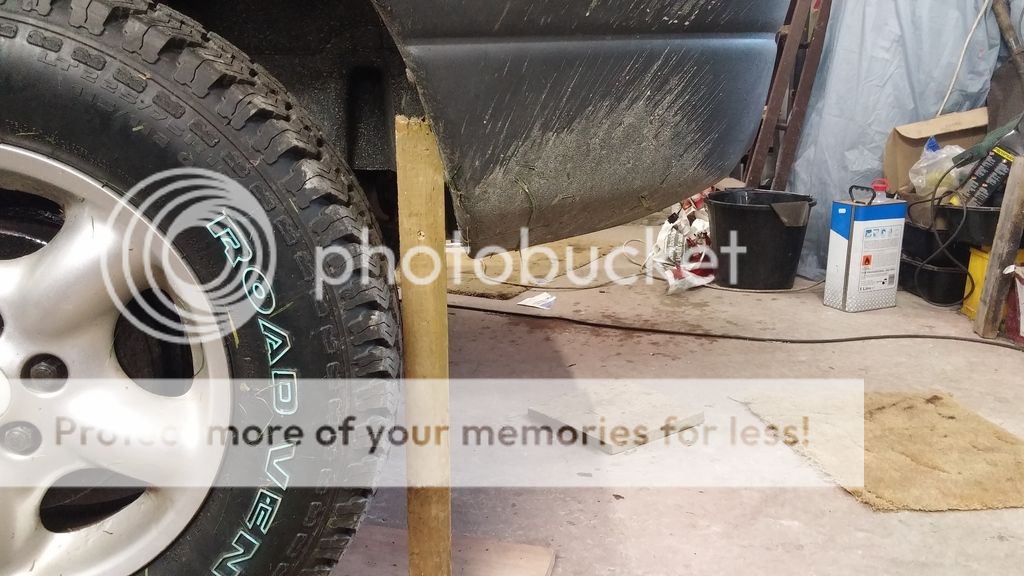
. This is down to experience in many cases after 45 years of messing with vehicles and 60 years of life in general. - and marriage lol :rolleyes:

Joe
 
Last edited:
You do look to have a bigger gap at the rear of the arch than my calculations resulted in! Given the geometry of the setup on my car and tyres having a 1" larger radius though I'm sure there is no room for extending the trailing arm. Maybe I made an error somewhere.

As you say - would be good to put a back wheel on a ramp, or jack it up and see where it goes :) Would be interesting as well to see how much lower the trailing arm bush at the wheel is than on the chassis (when at rest).

I don't think lowering the mounting points for the suspension is an option - that rather negates some of the benefit of the lift!
 
Joe I think your gettin yourself in a tizzy. I drove a Disco 1 about 25 years ago and it was the most dangerous car I've ever driven. I'd be very shocked if my Freeby is anything like as dodgy as it was on a motorway. And as for testing under emergency braking I can test that anytime on a quiet road.
Chill mate. It'll be Grand. ;)
 
Yes I have to say I've had a few very scarey moments in Discos at motorway speeds - I'm sure even a Freelander that's not quite perfect will be much better.

Anyway, when you slam the anchors on the front will compress, so it'll be like normal - mind you the back axle will probably tuck under the car like the old Heralds/Vitesses :)
 
Back
Top