L90 BCM
Active Member
- Posts
- 328
- Location
- War-wick-Shire land
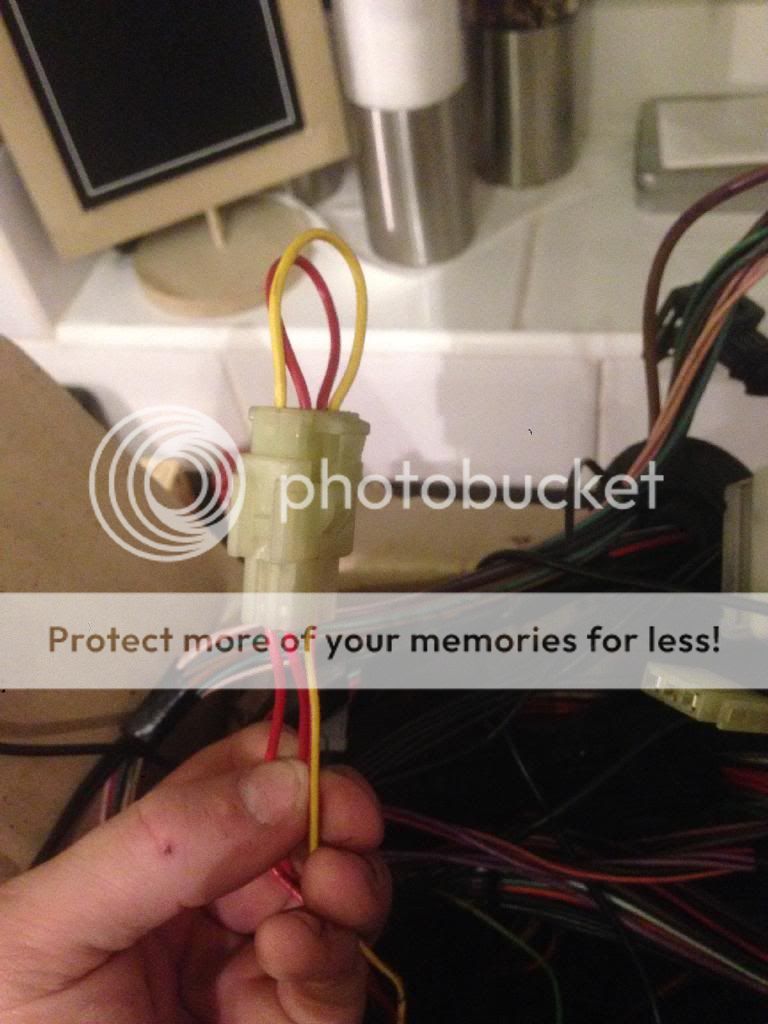
Hi all I am in the process of stripping down my wiring loom and wondered if someone knows what this bit is for?
I have searched and I think it is where you can plug in a relay to prevent a caravan from draning you car battery when the engine is of. If so does any one know where I can buy it from? Thanks Ben
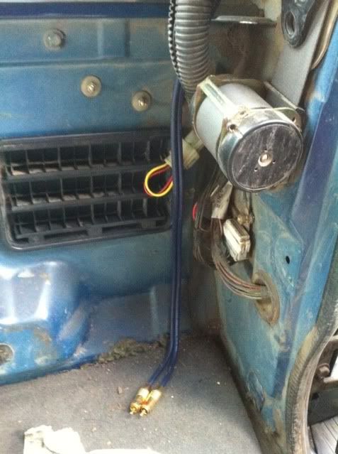
I think it normally sits in the back corner , not sure as it's out of the vehicle now lol
I have searched and I think it is where you can plug in a relay to prevent a caravan from draning you car battery when the engine is of. If so does any one know where I can buy it from? Thanks Ben
I think it normally sits in the back corner , not sure as it's out of the vehicle now lol


") just what I was after, at least I know that it needs be be there and stay connected
just what I was after, at least I know that it needs be be there and stay connected 

