- Posts
- 12,163
- Location
- Sud ouest France !
normaly is when ive cut my fingers on some sharp edgeNope, our mate meant a red device, didn't you @badfluffy
Often easier to go round looking for corroded connectors or defective earth points than searching for a needle in the electronic. haystackI might be missing the point of some of the ideas posted here so if that's the case I apologise and please help me to understand what you mean. A couple of bits suggested have been bad earths, corroded connectors and scanning so let me explain my thoughts on those for you to pick the bones out of:
The way is see this is that before I can make any meaningful progress, I have to narrow the field of investigation here, the common denominator is communication between nodes so I feel I have to find the one that is causing the issue. Be that a bad earth to it, corroded connector or whatever, it simply can't be everything. If I don't disconnect them all to find the one that is causing it, how do I move forward?
I can scan each device individually but the result is always the same. Everything single node is in fault. I have stripped a fair bit of the dash out today, disconnected the instrument cluster and scanned it again everything else remains in fault so I can fairly safely say that it's not that device causing the issue. It is also not the CD changer either as that was out at the same time. I can't find the suspension module though, all YT videos seem to suggest it is in the passenger footwell but there's nothing there in my car so maybe on the 2010 it has moved?
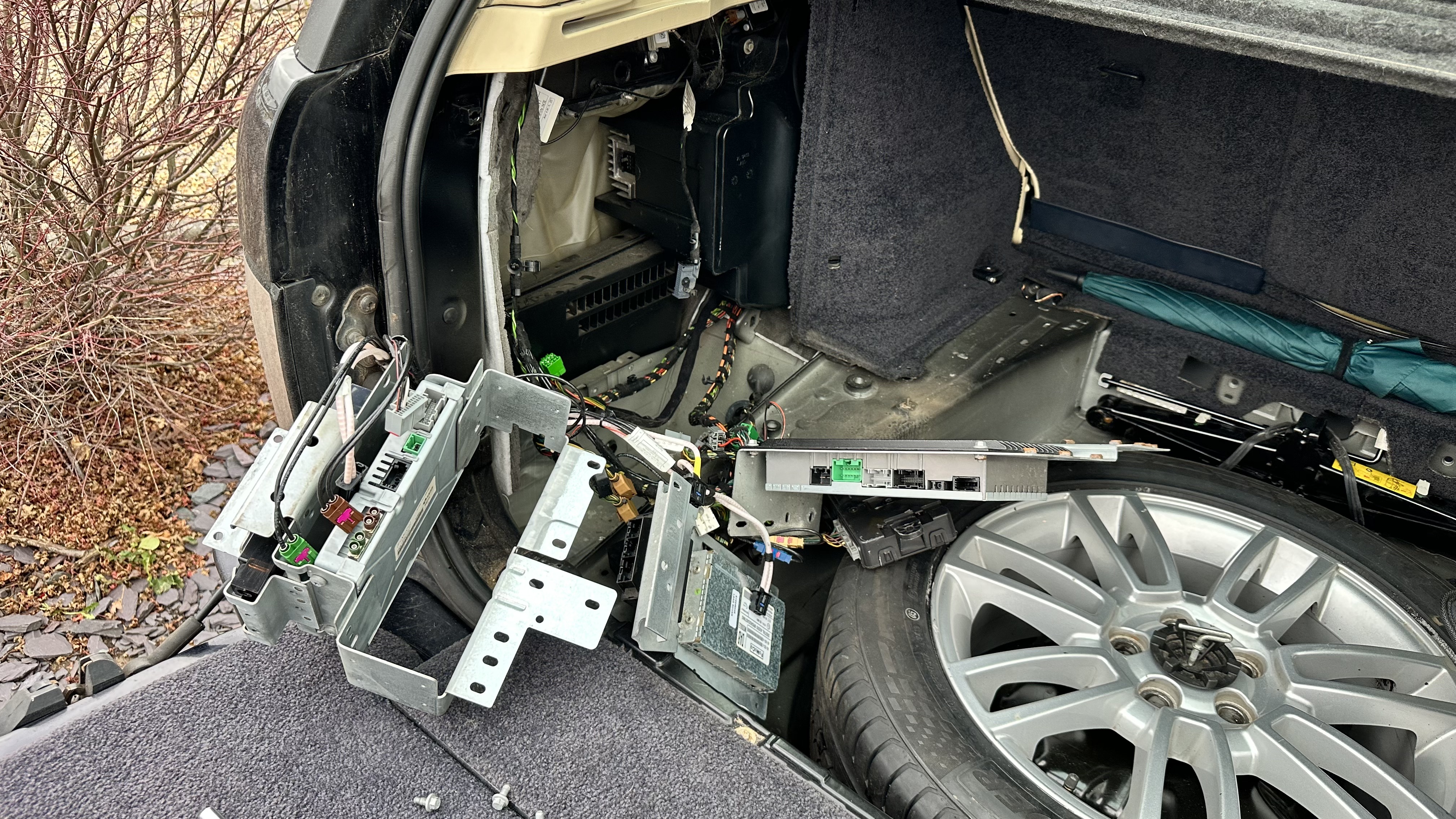
As time allows I will strip the boot out and just go through everything I can find to disconnect there and retest. I take on the point about serial CAN devices but even so it will help me get closer surely. Amazingly, the only thing that never has any faults is the engine ECU. That is clearly a separated item.
Thanks for the suggestions though, keep 'em coming. I have to fix this, it can't beat me.
They all talk to each other Dan, one module that finds fault can cause errors through the network.I don't have one of these more modern JLR nightmares so please forgive me.
All of these very clever ECU's report back to HQ who formulates all the info into warning messages on the console and into readable logs for diagnostic tools.
I would think either "HQ" has gone "duff" OR HQ is OK but the telephone lines down to all of the sub-departments is hosed.
I thought there were several "Buss-es" CAN, K etc.
If comms is down then the central HQ brain is going to think they have all perished under enemy attacks and report their demise to you wholesale. Is there a "Buss Tester" tool to check comms is working on each of the communication busses?
Are some of them Optical? Has a connection been disturbed, leading to a major disconnect?

GapIID, iCarsoft Max and Launch CRP123, yes all have worked fine before.What diagnostic tool are you using? has it worked ok on this car before?
Yeah, and that pretty much agrees with my plan of disconnecting until I find the culprit (or eliminate them from enquiries). Feels more like looking for a needle in a stack of needles right now.Often easier to go round looking for corroded connectors or defective earth points than searching for a needle in the electronic. haystack
Not sure you can just disconnect modules as they are I think all interconnected.GapIID, iCarsoft Max and Launch CRP123, yes all have worked fine before.
Yeah, and that pretty much agrees with my plan of disconnecting until I find the culprit (or eliminate them from enquiries). Feels more like looking for a needle in a stack of needles right now.
If I narrow it to say, the RLM for example and it is actually a dodgy sensor I should be able to disconnect that ECU, and (I'm hoping here) have all other issues resolve until I plug that back in. Then I can look at connector/earth wiring shorts etc. and other sensors related to that area until I find the particular needle.
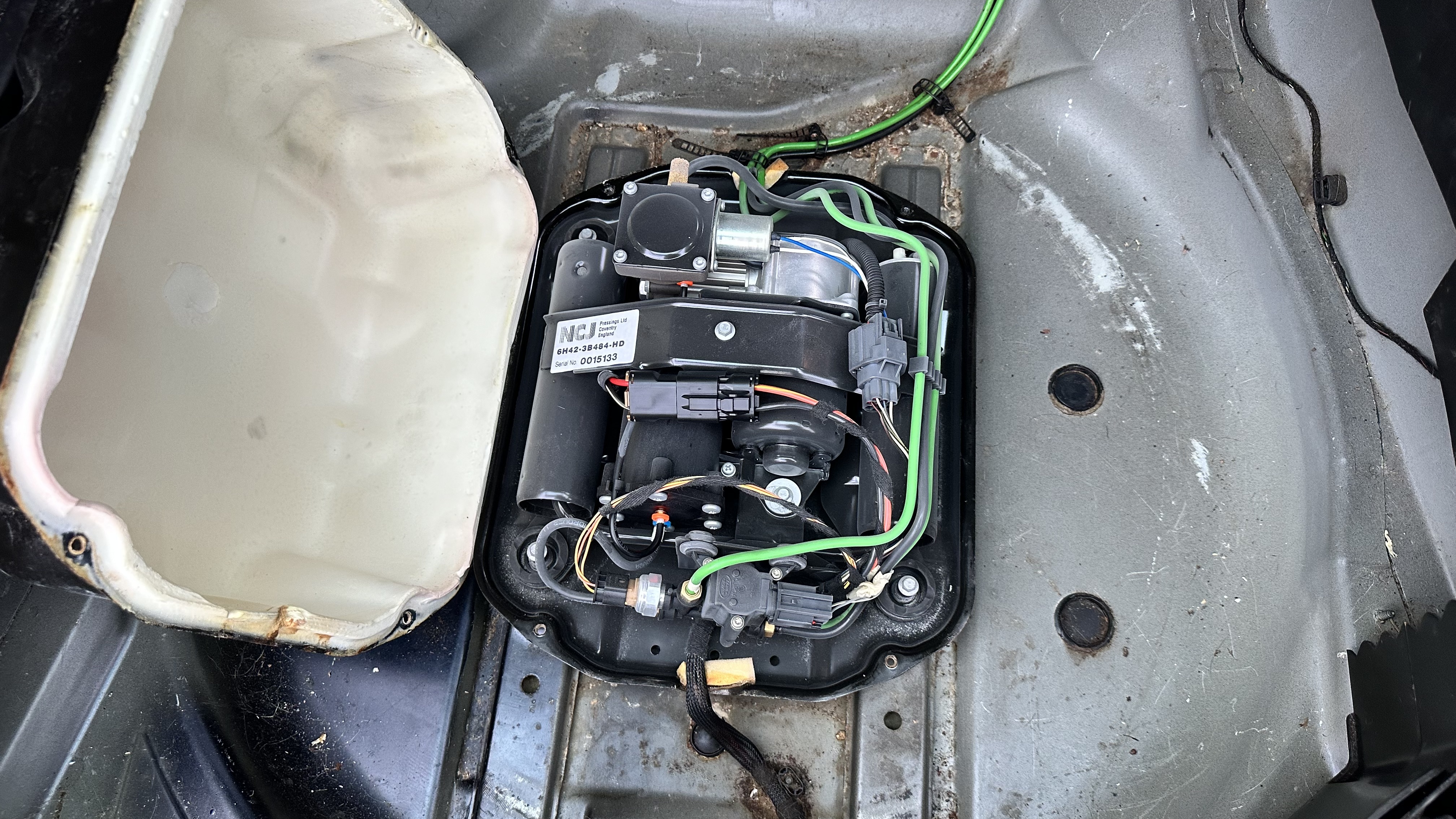
I'm going to start again in the boot as there are several there that I didn't get to remove. When I man up enough to lift the spare out I can get to the compressor which seems to be working fine but must be connected as I can view the temperature of it and the motor etc. so all that comms has to be there.
Still not found any water ingress yet which is a double edged sword as I am pleased it doesn't leak (that I can see) but also hasn't helped my narrow the search either.
Does anyone know where the Ride Level Module is in the 2010? It's not where all the web resources suggest as per the <2009 cars in the passenger footwell typically.
So far it has been ok to disconnect individual modules. They obviously fail and show "not fitted" but I can live with that as I should get comms to other devices. I've never come across anything aside from the fibre stuff that loses comms to all other devices if you remove one... Until perhaps now I guess.Not sure you can just disconnect modules as they are I think all interconnected.
No, not a chance but this issue started before the battery was replaced anyway.When the new battery was fitted, the terminals were not connected incorrectly, even for a millisecond? Or a battery charger connected incorrectly? Or has it been jump started from another vehicle with an engine running?
GapIID, iCarsoft Max and Launch CRP123, yes all have worked fine before.
Sort of, iCarsoft will no longer talk to the car but the others all do and that now includes a £2k Autel (I think that was the brand)Do they all report the same faults?
I am almost at the point of begging for help to locate all the modules now. This is the route I want to go for narrowing the field, I may be wrong but it is the only way I can see to do it. Can anybody help me with a location map of them all for the 2010>2012 L322?
Air suspension is the main one my friend. All online detail suggests it's at the bottom of the A pillar but it's not and they are always <2009 cars. I can't find RAVE for the 2010> either, can you PM a link for it if you have it please?Are there any in particular you are having trouble finding?

L322 - MOST system parts
Hi, Help needed . 2012 Vogue 4.4 Diesel. MOST system head unit has been diagnosed as faulty / not sending any signal. Need to find a replacement unit(hopefully eBay). Has any got the part number for the head unit as struggling to find . Any help greatly appreciated.www.landyzone.co.uk
This thread is for the MOST ring but does list some modules.
I will take a look at my files for 2010 & 2011 and see if there is a layout.
Have you actually tested your CAN lines with a meter? I believe there are some simple test you can do.
J
Welcome To LandyZone, the Land Rover Forums!
Here at LandyZone we have plenty of very knowledgable members so if you have any questions about your Land Rover or just want to connect with other Landy owners, you're in the right place.
Registering is free and easy just click here, we hope to see you on the forums soon!
")