Discovery Rust - Boot, Sills and Wings

This site contains affiliate links for which LandyZone may be compensated if you make a purchase.
I used these bolted thru the 10mm plate in the pic then the bolts welded to prevent em from coming undo or pulling thru.. each one is rated at 3.5tonnes SWL so given the safety factor built into lifting gear good for a breaking strain of nigh on 15tonnes.


DSC_4148.jpg


IMG00641-20120315-1430.jpg


IMG00639-20120315-1359.jpg
 
how about lifting shackles for printing machines/other heavy machinery, iv got 2 on my rear bumper, rated at 16t i think and welded from behind bumper and around the sides, taken alot of stick so far

That's a good idea, I may just look into that.

Need to do something tomorrow as I'm out on Sunday around Guildford lanes
 
Morning all!
Crikey, What a thread! I bought my first Landy a few weeks ago, thought I'd come online to check up about tyres, now im reconsidering the whole build!! :scratching_chin:
Well done and a big thanks to Hornet and to all the other guys who have passed on info and photos in this thread.

Back to the points in discussion though
It is impressive what the jate rings will take, but as with all off-road engineering, its got to look strong enough to inspire confidence. For me anything jate ring related doesn’t inspire much confidence even though i know it should take the stress.

I do like the look of the securing eyes as above, just need to make sure that they are large enough to be able to fit shackels. Looking at the male stud type above, they will allow a small amout swivel if the nut isnt tightened too much. Stainless washer each side and away you go.

I just need to make a bumper to fit them too now!
 
i wouldnt leave them loose, iv got 2 welded to my rear bumper with 2 shackles, (only need to be big enough to fit bolt through, iv been winched sideways off them and dont need swivel, i toyed with the idea of making some of the swivel points for front bumper like first four make but decided against it, im going to put some more of the above on, probably male with spreader plate behind wedled in place, if you put 2 on theres no reason you cant attache both to recovery to spread the load with a short strap etc.
 
Just for the record as I agree that any item needs to look the part unless you know your stuff, to inspire confidence.

The standard front bumper on the Discovery is attached to the chassis with 2 10mm bolts per side. the standard bumper thickness at this joint is 3.5mm. The allowable bearing force per side on the bumper is thus 4 x 600kg = 2400kg per side.

The allowable bearing force per side on the 2mm chassis is 4 x 340kg = 1360kg per side. But the section is reinforced. So let's assume that the allowable stress is the equivalent as the tensile strength, without a safety factor, for the 2mm section. ie Allowable force = 1360 x 3 = 4080kg per side. The allowable shear force per side (with HT bolts) is 4 x 2348kg = 9392 kg per side. The lower section has a reinforced bolt hole through 4.5mm material. Again, removing the safety factor to compensate for the reinforcement, we get
Allowable bearing force = 2 x 770 x 3 = 4620kg per side, and Allowable bolt shear force = 2 x 2348 = 4696kg per side.

Therefore, the front bumper can be reinforced so that the attachment material at the bolt section is 6mm thick, top and bottom. Then an eight ton force can be applied to the bumper, 4 ton each side, IF the bumper has decent attachments welded to it.

A jate ring, or similar attachment can be attached to the horizontal bolt in the lower section. Again, the applied force should be limited to 4 tons per side.

So there you go, I have reinforced the chassis at the connection point and I have two reinforced brackets on the winch tray which is 8mm to 6mm using m12 bolts each of which can take 4225kg of force in shere. I am confident that the bumper ain't gonna move its just the point that I a trying to understand.

AND THIS IS THE POINT- how much do you understand about recovering your vehicle?

A simple question on recovery to set our brain juices flowing over the weekend.

You have two recovery points on the front of your vehicle. You have a bridle strap connecting the two. You have a steady pull on the bridle strap of 1000kg

QUESTION what is the kg force that each recovery point is subjected to?
how long is the bridle strap?
is the 1000kg steady pull a maximum? ie, cannot exert any more?
what are we being recovered from?
in an ideal world, the load shared on the recovery points is halved, so 500kg each, but this rarely happens.
 
Just for the record as I agree that any item needs to look the part unless you know your stuff, to inspire confidence.

The standard front bumper on the Discovery is attached to the chassis with 2 10mm bolts per side. the standard bumper thickness at this joint is 3.5mm. The allowable bearing force per side on the bumper is thus 4 x 600kg = 2400kg per side.

The allowable bearing force per side on the 2mm chassis is 4 x 340kg = 1360kg per side. But the section is reinforced. So let's assume that the allowable stress is the equivalent as the tensile strength, without a safety factor, for the 2mm section. ie Allowable force = 1360 x 3 = 4080kg per side. The allowable shear force per side (with HT bolts) is 4 x 2348kg = 9392 kg per side. The lower section has a reinforced bolt hole through 4.5mm material. Again, removing the safety factor to compensate for the reinforcement, we get
Allowable bearing force = 2 x 770 x 3 = 4620kg per side, and Allowable bolt shear force = 2 x 2348 = 4696kg per side.

Therefore, the front bumper can be reinforced so that the attachment material at the bolt section is 6mm thick, top and bottom. Then an eight ton force can be applied to the bumper, 4 ton each side, IF the bumper has decent attachments welded to it.

A jate ring, or similar attachment can be attached to the horizontal bolt in the lower section. Again, the applied force should be limited to 4 tons per side.

So there you go, I have reinforced the chassis at the connection point and I have two reinforced brackets on the winch tray which is 8mm to 6mm using m12 bolts each of which can take 4225kg of force in shere. I am confident that the bumper ain't gonna move its just the point that I a trying to understand.

AND THIS IS THE POINT- how much do you understand about recovering your vehicle?

A simple question on recovery to set our brain juices flowing over the weekend.

You have two recovery points on the front of your vehicle. You have a bridle strap connecting the two. You have a steady pull on the bridle strap of 1000kg

QUESTION what is the kg force that each recovery point is subjected to?


baffles me, but would it be 1000kg split over the 2 points?

also would it depend if you had an even pull ie no more pull on 1 side to the other?
 
how long is the bridle strap?
is the 1000kg steady pull a maximum? ie, cannot exert any more?
what are we being recovered from?
in an ideal world, the load shared on the recovery points is halved, so 500kg each, but this rarely happens.

Got my mate who has took physics at uni and we worked out at a v8 at full beans going 15mph with a kenetic rope required just shy of 8t breaking strain providing it was on a flat surface both at std mass. And the non moving vehicle started mlving at the 1st pull
 
Oh this is interesting -

Ok the pull is steady at 1000kg and can't go up or down.
The bridle strap length is dependant on you as its you that rig it up so tell me (its part of the answer)

The load is not halved and that is the fatal error many people make.
 
i didnt think it would be as its the same load just spread accross 2 points, but i left physics a looong time ago, im interested and intregued by the answer will be though :)
 
Oh this is interesting -

Ok the pull is steady at 1000kg and can't go up or down.
The bridle strap length is dependant on you as its you that rig it up so tell me (its part of the answer)

The load is not halved and that is the fatal error many people make.
:D
577kg per recovery point.
i may have to adjust my bridle, depending how far apart your eyes are
 
How can 1000kg of load at the rope/winch rope etc magically become more load at the bumper just because it is spread over two points.

At equilibrium the loads felt by each vehicle would be the same irrespective if how many recovery points were fitted to each vehicle, so I would say that the load at each recovery point would be somewhere between 0 and 1000kg each where the total load is 1000kg felt by "the vehicle" at any one time, because that is the load being applied to the bridle "system" and assuming that the bridle system is not kinetic it cannot be applying or absorbing any energy so would therefore allow 1000kg total to be felt between the two recovery points.

If this is not true then that why I found Mechanics modules very hard!
 
Or is it something to do with the bridle exerting a force pulling towards the centre of the bumper aswell as away from the bumper in the direction of the recovering vehicle?
 
Nrgserv, way to go dude, not badvand very close, assuming the optimal bridle angle of 45 degrees is achieved.

Answer explained

Let's use a simple force of pull of 100kgs.

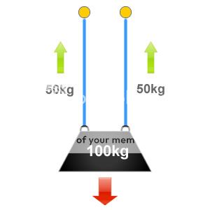
A single strop to a single recovery point exerts a force of 100kgs.

Now lets use two strops. If two strops are connected to two points on both vehicles then you get a shared force as there are no internal angles. As below.
657f2433538d41099afc46dde23dd2b6.jpg


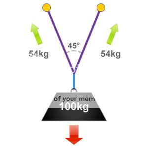
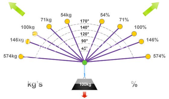
Now lets use the bridle. As the internal angle between the recovery strops increase then additional forces (vector forces) begin to be applied to each sling / anchor point.

When rigging recovery strops the 'ideal angle' is approximately 45°, at the ideal angle there would be 54% of the applied force being distributed to each recovery point. Although this is over half of the original weight of the pulling force, we have still gained an advantage by sharing it between the two anchor points.

17f5d2ffc1029d33473ae7b7b2426b1a.jpg


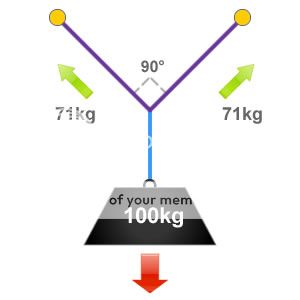
Now lets see what happens when we alter the internal angle. An internal angle of 90° between strops is sometimes referred to as the 'OK' angle. At this angle 71% of the pulling force will be distributed to each recovery point, so in this example that will be 71kg.

It is often easier to roughly estimate a 90° or right-angle when undertaking rigging tasks. By staying at or below this angle ensures that we don't load our recovery points with excessive forces.

70a480e583ef39d2ebd02562efc5c7af.jpg


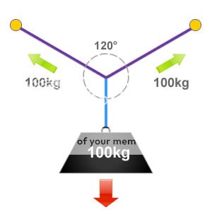
Now we have a critical angle. A basic way to understand the effect of vector forces is to imagine that if a full circle equates to 360° and this was split into three equal parts we would end up with three angles of 120°, as show in the illustration below. An internal angle of 120° is also defined as the 'critical angle'.

Because everything is in equilibrium at the critical angle of 120°, whatever the pulling force, this is what we will be exerting to each recovery point and each item of rigging equipment. So in this example it is 100kg or 100% of the pulling force.
2d8bcdfb28a8738914533abd9f5a129e.jpg


Once you past the critical angle, the pulling force to each recovery point is increased and the image below explains that.

2fe190d9b14a517f1c6b83c1cc8d49f3.jpg


So the you go. Next time you think about tugging hard on a rope with another land rover, think about how you are exerting the forces. A land rover exerting 8 tonnes in the wrong configuration can actually exert almost 46 tonnes to your recovery points.

Phew
 
Back
Top