Discovery Rust - Boot, Sills and Wings

This site contains affiliate links for which LandyZone may be compensated if you make a purchase.
have you seen those digital protractors that wheel alignment guys use?

magnet it onto the diff flange and it tells you the angle away from perpendicular! NOICE!
 
But he is looking for the difference in angles away from vertical of the transfer case flange face and the diff flange face, ie, how far out of parallel are the two flanges?

There is no way the front diff flange is supposed to be parallel to the transfer case flange though because I think that would result in far too much caster.

The only operation that is required to decide how far out the axle is is to measure how far away from horizontal the spring seats are, or at least, how far away from parallel the axle and chassis spring seats are.

Land rover designed the transmission in such a way that the prop flange relation was different for the front and rear props.

It is also of interest though that the front prop has its yokes set 45 degrees out whereas the rear prop yokes are set in the same plane.

This may be something to do it.

Cheers :)
 
This is what i am talking about
ScreenHunter_24Dec181739Ian.jpg


Diagram 1 shows what a normal relationship between drive flanges is set at, however as Noisy says, LR designed it different.

Diagram 2 shows an indication of + or - degree explanation so we are singing off the same sheet. For instance if you say that the front pinion carrier flange is +8degrees then I can set it easily as it is pointing up. -8 degrees would have it pointing down.

The spring seats should be horizontal as Noisy says, however when I set mine to Horizontal I need to know how much off from std the angle is. Obviously mine is modded and I dont know anyone with a std disco lol.

Cheers for your help.
 
Easiest way of measuring it would be with a spirit level app on a smart phone against the drive flange as that tells you the angle and you can calibrate it to a known horizontal or vertical.

You're assuming that land rover actually put some thought into a design rather than just some chaps in Solihull throwing some bits together, seeing if it worked, then declaring victory over a pie and peas at the local pub! :scratching_chin:
 
Green, just remove your prop and jack your diff drive flange so its ctr is 35mm above the ctr of your hub, then measure your angle. If that wont work ill have a crack at whipping my shaft off tomorrow
 
Green, just remove your prop and jack your diff drive flange so its ctr is 35mm above the ctr of your hub, then measure your angle. If that wont work ill have a crack at whipping my shaft off tomorrow

Cheers but please don't whip your prop off mate, too much hassles for you.

Where did you get the 35mm from?mi haven't seen that anywhere that I looked :confused:
 
Moving on to today's job, I finished the extra mounts for the front bumper. As mentioned earlier, I found that when winching in to stow the hook, the winch when going tight, could move the bumper slightly. At present I only had the std four bolt fixings so I decided to reinforce the bumper mounts.

I needed to ensure that the bumper could take a significant hit from the front without moving and to do this I welded on two more mounts that would fit directly to the winch tray.

If you have seen the winch build then you will see that I welded an 8mm THK plate to the front chassis to take the winch. The new mounts secured to this and therefore will transmit any force straight to both legs of the chassis which is basic mechanics. The chassis is more than strong enough to take heavy impact and any impact that can deform the legs will leave me not bothering as I will be in a coma lol.

Here's some pics.

First off the winch plate. Here you can see the holes for the mounts. 1 10mm and 1 12mm bolt per mount.
72593c88bbeaa0d427828dc786a1bd53.jpg


Here are the months themselves. Basically I used the last of my 6mm THK angle. With the bumper bolted in place to the chassis legs, I placed the new mounts in position and clamped them to the bumper. Then I drilled the holes and bolted them in place. Whilst still clamped to the bumper, I tacked the nuts in position and then tacked the angle to the bumper.

I then removed the bumper complete and seam welded the mounts

508b3b49be24b92405423ff306decd4a.jpg


fac2ef563eced830d74b7ba6907b9663.jpg


d76991ca623f10ac96702bf0065b0649.jpg


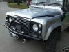
Now it's all together and a quick test by driving into a tree resulted in 100% success.lol

Now the next thing is to finalise the recovery points, so any suggestions? What do you guys use?
 
Like that mod .. Going to do that, or similar, to mine when I've got the winch properly sorted .. and made a new bumper! Think mine will also bolt to the winch mounting plate too. ;)

Use some 8 or 10mm plate welded onto the bumper front, each side just outboard of the chassis legs, with holes cut that are large enough for either Shackles or a recovery hook .. like these ..
 

Attachments

  • bumper.JPG
    bumper.JPG
    22.6 KB · Views: 200
  • bumper2.JPG
    bumper2.JPG
    21.3 KB · Views: 239
PaulD - I have I thought of that, I have some 8mm plate so I may do something like that. Cheers.


Gib - I have read almost all the articles on swivel adapting etc but tbh it would be nice to get a hold of something that would just bolt on and at a descent price other than hundreds of pounds for new arms. No one caters for the guy that has little disposable cash anymore and when you do have cash to spend, you get **** customer service.

I am aiming to have a bolt on solution available for a lot less than silly caster correction bushes which are another pain in the arse to fit.
 
What about dropping the mounts on the chassis? 50mm lift =50mm drop on the chassis?

Obviously your loosing 50mm ground clearance at those points but surely there is something else lower anyway?
 
Well if you have a Bronco you can get adapters that do this although, like you say, you loose clearance underneath.

What you can do is lengthen the radius arm and move the mount rearward as this has a similar effect. It also helps with the articulation too as it is easier on the bushes. Its a std trick on Suzuki's and one that if I had the equipment and space, I would do myself.

Back to the recovery points, I am looking at something simple like this out of 8mm plate doubled up
ScreenHunter_25Dec191726Ian.jpg


It will fit to the bumper as so seam welded all round
ScreenHunter_27Dec191745Ian.jpg


I am working on another idea as we speak and will post after dinner. Ummm my homemade Chicken Curry cause' im a bitch man wife lol
 
Those recovery points would be just fine, pop a nice big bow shackle in there and you're into a winner.

I use those swivel recovery points but I imagine they are limited capability and I doubt your see them on a competition vehicle.

Yes have seen vehicles with modified suspension before where the front arms are joined to the chassis further rearward than the rears, ie the arms actually cross eachother on the way to their respective axle.

Better for geometry I believe!
 
Back
Top