So according to my schematic,
On c0230( instruments) pin 9 the AC pressure sense sends a 0-5v signal . The instruments sends the data over canbus to the engine ECU for ideal control, cooling fan speed control and AC compressor clutch cutout.
Also on c0230 pin 20 the AC evap sense input is sent from the instruments over canbus to engine ECU.
On c0233(instruments) pin 13 AC sense input, the instruments sends that input trigger as a message over the canbus too
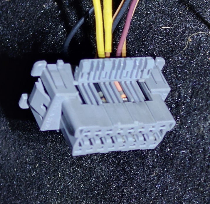
Although it says td4/Nas for the evap and the pressure sense, all the wires were in the connectors that came with my 1.8 instruments!
On c0230( instruments) pin 9 the AC pressure sense sends a 0-5v signal . The instruments sends the data over canbus to the engine ECU for ideal control, cooling fan speed control and AC compressor clutch cutout.
Also on c0230 pin 20 the AC evap sense input is sent from the instruments over canbus to engine ECU.
On c0233(instruments) pin 13 AC sense input, the instruments sends that input trigger as a message over the canbus too
Although it says td4/Nas for the evap and the pressure sense, all the wires were in the connectors that came with my 1.8 instruments!
")