Rotaxengine

New Member
Hi all,

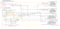
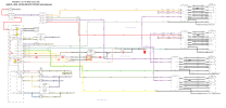
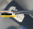
I have a Freelander 2 (2014 reg) and I’m trying to find details of the wiring/power connections for the tailgate latch (4-pin connector). I’d like to know which terminals I can power to operate it independently via an external switch.

Background: the latch has been unreliable for months. My garage replaced the micro-switch, then later the complete latch assembly, but the fault remains. They suspect a control unit issue but couldn’t get a wiring diagram from Land Rover.

If anyone knows the correct pinout or a way to test/activate the latch directly, I’d really appreciate the help.

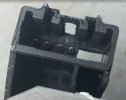
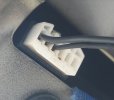
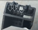
There are 3 black wire to the 6 pin connector
Thanks!
 
Last edited:
I'd guess the wiring is the same as the earlier model, as the boot latch is the same.
Hi,
Thanks for your reply. I am happy to accept the wiring is the same but do you know what the connectiona are?

The unit has three black wires going into it. I’m assuming one terminal connects to a 12V supply to operate the solenoid for opening the door. I also suspect that one of the other wires must be an earth, since the latch itself isn’t grounded (it screws directly onto the painted door without an earth connector).

I’ve already tried applying voltage to the terminals on the old unit—which, as it turns out, wasn’t faulty—but had no luck. What I’d like to do is find a way to operate the latch directly from the car’s battery, bypassing the electronics and the microswitch door-opening assembly.

Thanks
Ken
 
may help
 

Attachments

  • fl2 DOOR LOCKS.png
    fl2 DOOR LOCKS.png
    212.7 KB · Views: 7
Hi,
Thanks for your reply. I am happy to accept the wiring is the same but do you know what the connectiona are?

The unit has three black wires going into it. I’m assuming one terminal connects to a 12V supply to operate the solenoid for opening the door. I also suspect that one of the other wires must be an earth, since the latch itself isn’t grounded (it screws directly onto the painted door without an earth connector).

I’ve already tried applying voltage to the terminals on the old unit—which, as it turns out, wasn’t faulty—but had no luck. What I’d like to do is find a way to operate the latch directly from the car’s battery, bypassing the electronics and the microswitch door-opening assembly.

Thanks
Ken
Here's the page from the diagram.
Screenshot_20250825_225901_Adobe Acrobat.jpg


Pin 1 is the motor drive from the BCM. Pin 2 is the earth path for the interior light sense circuit. Pin 3 is the ground for both the motor and interior light sense line.
 
So what is happening with the tail gate ?is it not opening at all, is the latch not getting any power to it, can you hear the latch clicking when you press the open door on the fob.

Also have you tried just the rear tail button on the fob on it's own?
LdfvOY8l.jpg
1
 
Here's the page from the diagram.
View attachment 348512

Pin 1 is the motor drive from the BCM. Pin 2 is the earth path for the interior light sense circuit. Pin 3 is the ground for both the motor and interior light sense line.
Hi, Thanks for taking the time to reply. I do not think this is the correct wiring diagram for my FL2! I have a diagram (attached) and as you will see it shows the relay - tailgate unlock. BUT it does not show any voltages or pin outs etc. I have measured the resistance between terminal 1/2 and 1/3 and the resistance is 15ohms - so would take a current of just over 1 amp. Terminals 2/3 is less than 1ohm. But we notice on the diagram there is or could be a PCB inside the unit!

There must be a way to opperate the unit via there 3 terminals.

My lath is part number LR072417


lruk1.jpg
inals
 
So what is happening with the tail gate ?is it not opening at all, is the latch not getting any power to it, can you hear the latch clicking when you press the open door on the fob.

Also have you tried just the rear tail button on the fob on it's own?
LdfvOY8l.jpg
1
 
The latch has been unreliable for months. My garage replaced the micro-switch as few months ago, then last week the complete latch assembly, which cost me £110 but the fault remains. They could not fix this and did not charge me labour. They suspect a control unit (the unit on the left hadside of the door under a tray) but couldn’t get a wiring diagram from Land Rover to measure outputs etc.

I am now straping the door down but was happy to drive the latch directly from either an external switch or knowing the correct terminals etc via the door micro switc and "cut out" the control unit

Fob and two button on dash do not do anything to opperate the latch.

Thanks
Ken
 
Pictures assuming they are of the latch connector ,so to unlock you would connect 12volts to pin 1 white/orange and earth to pin 2 .do not have the connection manual for FL2 so if anyone has could they post a link for it etc .
I would check that the connector does actually contact the pins as they look ( in the photo) that they do not protrude enough and may have been forced back
 

Attachments

  • lr1.jpg
    lr1.jpg
    138.4 KB · Views: 2
  • lr2.jpg
    lr2.jpg
    105 KB · Views: 2
Hi, Thanks for taking the time to reply. I do not think this is the correct wiring diagram for my FL2! I have a diagram (attached) and as you will see it shows the relay - tailgate unlock. BUT it does not show any voltages or pin outs etc. I have measured the resistance between terminal 1/2 and 1/3 and the resistance is 15ohms - so would take a current of just over 1 amp. Terminals 2/3 is less than 1ohm. But we notice on the diagram there is or could be a PCB inside the unit!

There must be a way to opperate the unit via there 3 terminals.

My lath is part number LR072417


View attachment 348515inals
The diagram is split into multiple sections. The page I posted is in the tailgate, at the motor connector.
The relay for the rear motor is part of the BCM, which can be replaced by someone with suitable experience of electronics repair.

To power the tailgate without using the BCM, you simply apply voltage to pin 1 of the connector at the motor, which will drive the latch.

It's been known for the wiring between the tailgate and body to break, which could be the issue.
It sounds like an auto electrician would be needed to solve this issue.
 
Last edited:
Pictures assuming they are of the latch connector ,so to unlock you would connect 12volts to pin 1 white/orange and earth to pin 2 .do not have the connection manual for FL2 so if anyone has could they post a link for it etc .
I would check that the connector does actually contact the pins as they look ( in the photo) that they do not protrude enough and may have been forced back
Hi, Sorry for the slow reply but I think you will see why!

Thanks for the details. Okay the photos I uploaded – one was the old unit showing pins etc and the connector was the new unit fitted to the door. Pins are fine.

I have tried the old unit as you suggested with 12 volts and the latch does not open. I have measured voltages at the new latch fitted to the car door. You can see I have inserted wires at the back of the connector

I have attached the details which I hope are clear. My test equipment is professional both power supply and meter so measurements are correct.

Note the clicking noise when testing.

It would seem that I do not get my 12volts to open the door on pin 1 But with the old unit 12 volts does not open it. Not sure if you saw this but resistance between 1 to 2 and 1 to 3 is 15 ohms so we only need an amp to open.
Thanks
wires.jpg
voltages.jpg

Ken
 

Similar threads