1976 series 3 rebuild

This site contains affiliate links for which LandyZone may be compensated if you make a purchase.
Right then, changing the handbrake gaiter, I decided to this before connecting up the handbrake as it meant I could move the handbrake around a little

This retaining plate has to be removed first
It is held in with 6 self tappers which require a flat bladed screwdriver to undo


The old gaiter can slide off


Rub vaseline on the new gaiter which helps prevent it cracking


I put the plate on first just because i thought it would help with lining up the holes


It can then be slid down the handbrake into position, might be worth sitting it in some hot water to make it more pliable as I got mine on and found it had split, was not pleased :(

The new fuel sender wires were then ran to the tank


The seatbox was then bolted to the tub and the floor panels slid in temporarily to check they cleared all the wiring and fuel pipes.


The battery tray and filter was bolted to the front


The throttle linkage was set at this stage. For setting the accelarator pedal position, my dad held the throttle linkage at full throttle and I bolted the pedal to the shaft tight whilst it was hitting the stop. that way when the throttle is released it should come up to its natural idle position :)

Today I put the seat on temporarily to see how it looks :)


Last edited:
Time for an update methinks,

Replaced the old tatty steel and rubber pipe for the heater matrix with some nice copper pipe which was of course polished when it went on :) Looks smart I think


Then we put the dash in, this is held by self tappers into the bulkhead (the plastic square trim pieces held in the steelwork with a hole for the screw to pass into)


Made some extra fly screens from some aluminium mesh we had which I think tidies up the dashboard a lot. These were cut to size and rivetted on


Making the switch panel, cardboard template:


Shape cut out of aluminium


Folded and roughly in place


The holes for the switches have been drilled and its been painted black. Switches are lucas ones to match the dashboard. (I'll get another photo again)

A shot off our wiring with new fuse boxes and relays (will make a cover for all this dont worry :)


Dashboard was wired up, tested and fitted. Only problem is cold start light is extremely dim (anyone know why this could be? :confused: )


And of course to prove our electrics work, the customary "light shot"


Any questions about anything we're doing, just ask :)
 
Great stuff and as said before, a good reference for those of us on a similar path. hope the exam results went well.
 
Great stuff and as said before, a good reference for those of us on a similar path. hope the exam results went well.

Glad people find it useful :)


Battery's gone on charge so will bleed the injector pipes and hopefully do a start up tomorrow
 
Last edited:
Looking great, I like the copper pipe idea for the heater feed, very smart. Are you keeping the standard steering wheel?

Yes we're keeping the wheel,looks nicer than an aftermarket one and I'd like to keep the interior standard ish with the exception of the housings for electrics :)


Be careful with copper pipe as if it is moving at all it will work harden and fracture.

Should be ok, theres a gap between them so they arent rubbing or chafing on anything and theres rubber hose on each end where it connects to the engine thermostat and heater matrix to help absorb vibrations (i.e. there is quite a bit of flex in the system). If it was all solid copper pipe then I would imagine there to be issues caused by vibration but it should be fine :)
 
Heres the pic of the finished switch panel


The yellow light is the low fuel light, the top right switch is interior lights and in the bottom row are rear worklight, front worklight and front spots (These need a light on them to show when they're on)
Started the engine up yesterday, the ignition barrel/ switch has a temperamental fault in it but when we wired in the ignition barrel off a disco temporarily the engine went first time :)

Bled the system and fired it up for a few seconds to check everything was right :) Now the rad and cooling system can be plumbed in properly
 
Right then, rubbed the 2 pack paint on the front panel down ready for painting, flipped it over and gave it a coat of blue (i'll do the front when its bolted to the chassis as its easier to put the radiator on with it flat on its front and painting it later means you wont scratch the paint :) )


The radiator was bolted to the panel using M6 bolts and nylock nuts and the plastic fan shrowd was then screwed to the radiator.

Once all this was assembled I put it in position on the chassis and connected up the bottom hose. (Before putting this on, I put the hose on the engine first, doing this means you only have to try and fit one end with the limited space available when the radiator is on)


I put the offside wing on temporarily so as to bring the panel upright when bolting it on (nothing to do with temptation making me want to see how it will look, honest :rolleyes:


If you remember way back before we started the bumper was painted in a thick coat of black hammerite. I want this to sort of look original ish so want it back to silver. I started attacking the thick paint with a scraper but that was no good so I put a flap wheel on the grinder and used that, strips the paint brilliantly :) Temptation got hold of me and I slid it in place to see how it looks :) Starting to look like a Land Rover again now :)


Tommorrows jobs hopefully are paint the front panel blue, give the bumper a couple of coats of red oxide and maybe spray it silver (so it matches the other cappings) and bleed the clutch :)
 
Have you fitted the rubbers that go between the rad panel and chassis absorbs some of the vibration and keeps it at right height.
 
Have you fitted the rubbers that go between the rad panel and chassis absorbs some of the vibration and keeps it at right height.

forgot about those tbh :) I will fit some when the blue paint's dry (its not bolted tight atm so not going to be difficult to do).

Thanks for pointing that out before I got any further :)

Quick question, the angled bits that hold the apron, do they go underneath the chassis or between the chassis and rad panel?
 
Update time!

Right then, yesterday we went to bleed the clutch but nothing was happening when the pedal was pumped down (i.e. the fluid level wasnt moving anywhere) but there was a sort of popping noise as you pushed the pedal past a certain point about halfway down. So we decided to investigate.

Took the cylinder off (making note of how far the nut is on the pushrod so it goes back in the same place). Order of dismantling goes like this:

Remove the dust cover,
Remove the circlip,
Withdraw the pushrod,
Hit the end of the cylinder on a wooden surface until the piston comes down and out of the bore

upon inspection, it was found the piston had got stuck in the far end of the cylinder due to rust/ corrosion so that when the clutch pedal was pushed down all we were doing was moving the push rod, not the piston (making the cylinder pretty useless)

Solution was to use fine emery on the inside of the cylinder and around the bit the pushrod pushes against on the piston. (below is a picture that shows the corrosion)


When the bits were cleaned it was reassembled in the opposite order to disassembly. The cylinder was fitted back to the tower thing and tested and it moved the fluid just fine so problem solved and it saved a few quid on a new clutch master cylinder :)

when doing this cylinder, its worth noting that the nuts that hold it on are on bolts and not studs, so you will have to use a cranked 13mm spanner to access the bottom bolt (which is the longer one) and you can use a socket on the top one.

We've had to give up on the defender servo as its just too big. With a bit of experimentation, we found a discovery servo to be an almost perfect fit on the brake tower and with it being a smaller diameter clears the bonnet with the exeption of the master cylinder feed bottle. Have got a series servo and master cylinder though which would be the better option I think if it will fit on the defender pedal tower. The observant among you may realise the brake pedal is a bit ddifferent to the others, so today my dad straightened it and welded on the old series pedal so it looks pretty much the same :)

Anyway, tonight a lot of the front end bits and pieces were at the front of the garage so I just decided to loosley fit everything and see how everything lines up, doesnt look too bad IMHO :)


And I put the lights in position temporarily to see how they look in the wing too :)

 
Right then another update after sorting through our servo problems.

a) the defender servo was way too big, there was no way at all it would clear the bonnet

b) We found a disco servo fits the tower but the reservoir on the cylinder is still too tall for the bonnet and as the master cylinder and servo had been outside for the best part of a year in the open we decided to get a series servo and master cylinder.

c) a series servo will bolt straight to the pedal tower, however the pedal itself needs modification and you still need to make a separate feed from the reservoir.

This post will just be basically how we got a series servo and master cylinder assembly to fit onto a defender brake pedal tower

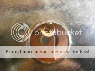
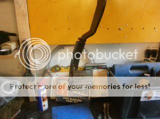
1) When the servo is fitted to the tower as is, the pedal sits just a bit too far back so you wont get the full pedal travel. Thats not the main problem however, you may notice that both the servo and the pedal have a plate with a hole in and one of them needs to be a fork to fit the servo properly.


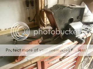
2) The tower was disassembled to get the pedal out. (the sharp eyed amongst you may notice that its the original series pedal welded on to the defender one, this is just to make it look better so it matches the other pedals :) )


3) A Plate with a hole in is welded either side of the pedal to make a fork


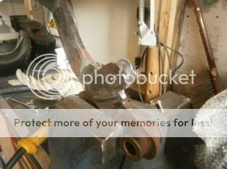
4) this photo shows how the servo end fits inside the fork. A pin with a hole in the end for a split pin goes through the holes in the fork and servo fitting


and a photo showing the series pedal on the end once painted black


5) The tower can be reassembled with the pedal and the servo was then bolted to it


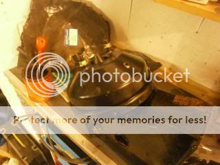
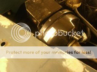
6) Master cylinder was bolted on and we found that although its a series servo, as its on a defender brake tower the wing still needs a bit of trimming for it to fit. This was carefully done with the grinder


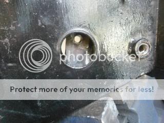
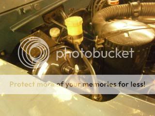
7) As mentioned previously, the reservoir bottle still sits too high for the bonnet to clear. If you open the top of the reservoir on the new cylinder you will see a threaded pipe fitting which will need a 17mm spanner to remove. We got a pipe fitting with a thread one end and on the other end a fitting for a rubber hose to fit on to go in the threaded hole where the reservoir once sat. As the original reservoir bottle had a rubber hose fitting on it, this was cleaned and brough back into service by bolting it to the bracket by the clutch cylinder


8) the defender pedal tower does have a slight angled bit at the top which we thought was fine but when we tested the bonnet fit, we found it to be catching the bonnet, making it unable to sit properly. a dust sheet was put over the engine bay and this was cut off with the grinder


The wing was then bolted on and tonight we got the passenger wing on too :)

Its starting to look like a proper land rover again now :)


Cheers,
Sam
 
Not much to report except after work I fitted the bonnet and I gave the grill a spray coat of silver from a rattle can


Horn, electric fan and the screen wash pump have all also been wired in by my Dad and are working from the dash switch :)

Will take photos of the bonnet fixings tomorrow after work
 
congrats on the thread making it to sticky status :D

Thanks :) Well you've been suggesting it for a while :D

Right then, yesterday we got the wings in grey primer


Another shot of the grill, will paint the background for the letters black at somepoint


The electric fan is in now too and wired up. It is held in place by 4 bolts with a rubber bit between the front panel and fan bracket


Wiring for the front lights has been run through conduit to keep it neat and clipped to the wing


The horn has also been wired in


also the screenwash pump and bottle have been reinstalled on the wing :)

 
Well good news all, after over a week trying to find the cause of a fault in the ignition system we appear to have sorted it, it was a dodgy contact on the starter motor where the nut had come a bit loose on a thread which isnt in great condition.

Started it up today and gave it a good run, tappets need adjusting now I think, going to do that tomorrow ::)

Also got the transmission tunnel and floor plates in yesterday, painted up the vent flaps and apron and started rubbing down the wings
 
Back
Top