I'm beginning to make a habit of answering my own questions on here, so for the benefit of future searchers, here's what I've just found:
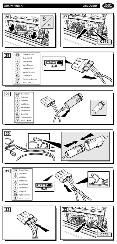
The wiring is indeed the official Land Rover kit - it's called the Auxiliary Wiring Kit, and there is a copy of the fitting instructions included on the Rave CD (aflt020e.pdf)

Now I just need to work out why the lamps aren't actually working...
Check that you are getting a live at the driving lamps.
They can be unplugged from the driving lights harness, behind the front grille - the live wire is Blue with a White trace.
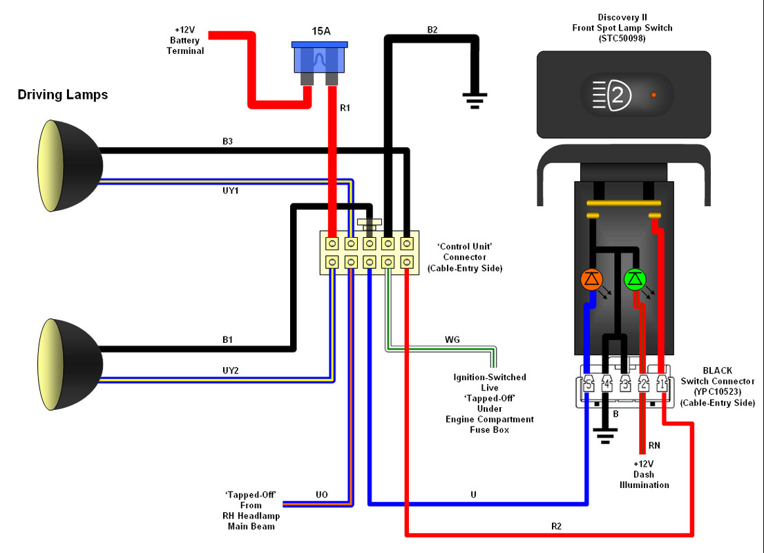
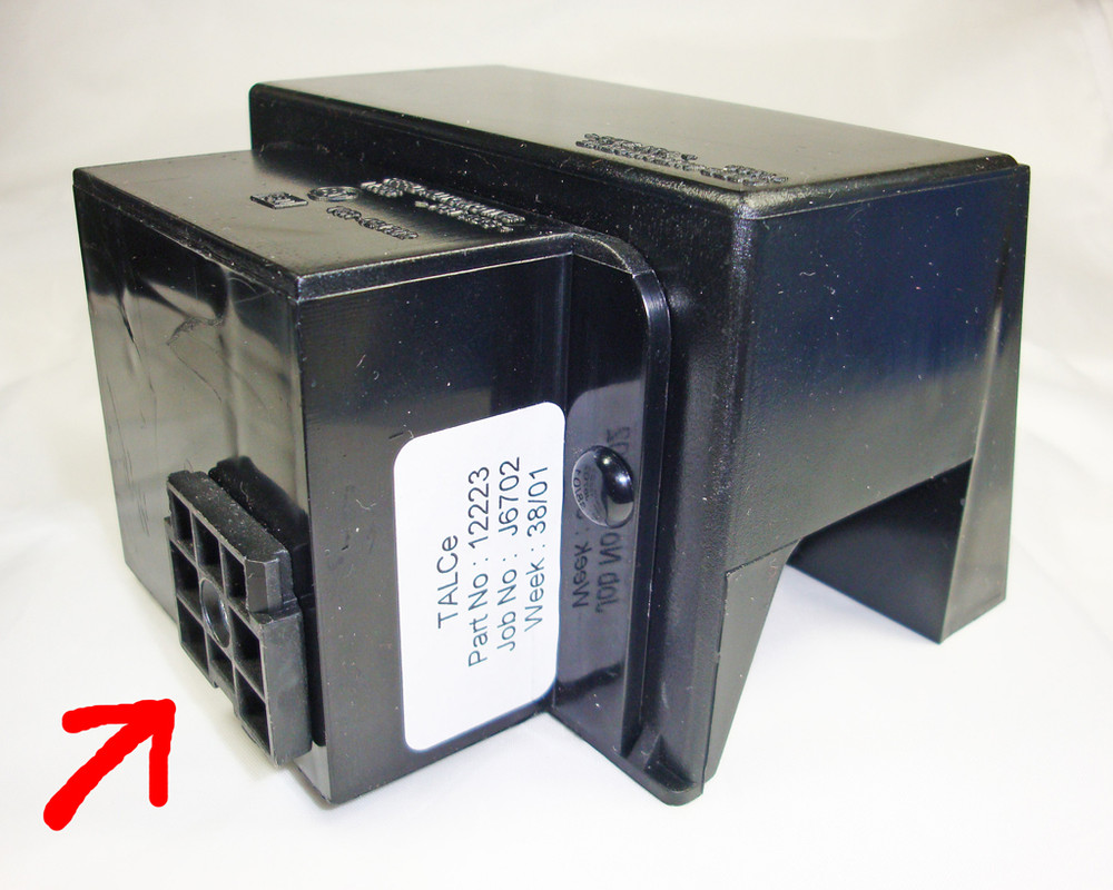
Your problem is almost certainly failure of the 'Control Unit' on the back of the underbonnet fuse box.
This unit is notoriously unreliable, and expensive to replace
It's part number -
VUB501690
Britcar (UK) Ltd > VUB501690 DRIVING LAMP CONTROL UNIT DISCO11 (G)
See also -
http://www.landyzone.co.uk/lz/f8/help-info-wanted-about-front-spotlights-199785.html
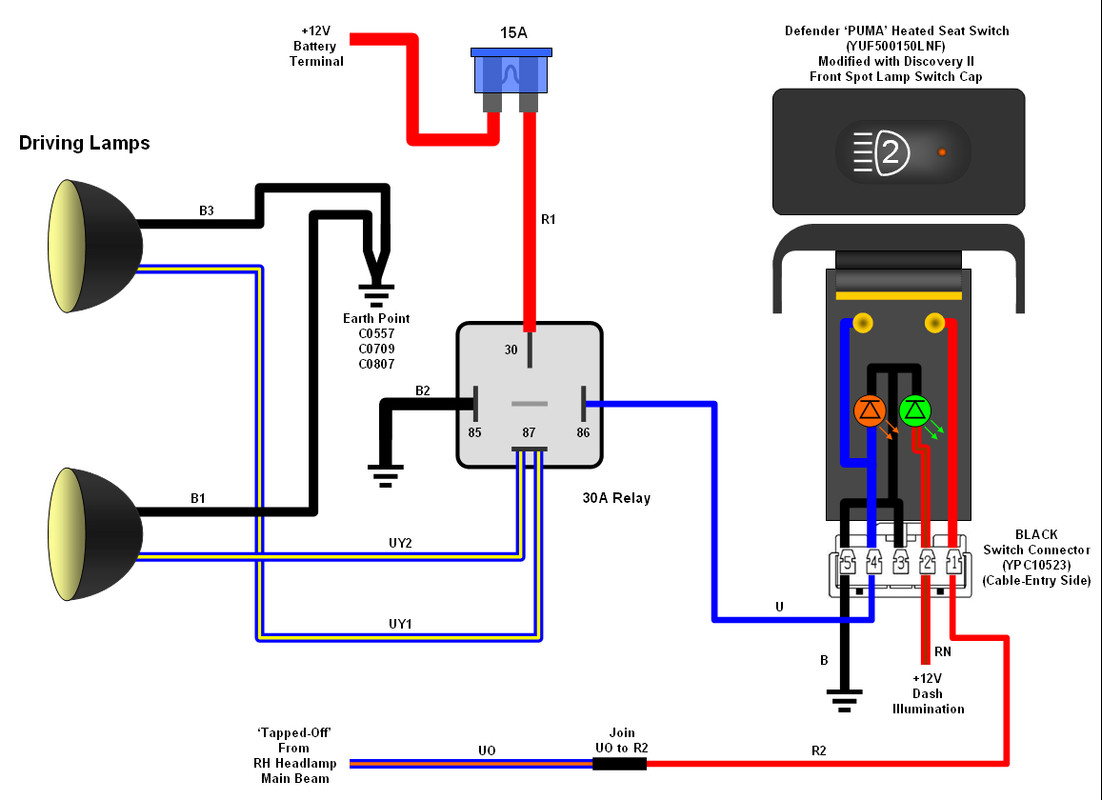
I would recommend changing it for a relay, it's cheaper and more reliable.
You do have to change the switch body for a latching live-switching switch, but for this, you can use a Defender Puma Heated Seat Switch (
YUF500150LNF), which is only a fiver
The Driving Lights Switch's 'Aux 2' front can be easily swapped to the Puma switch body.
If you want to change to a relay, you might find this useful -
Wire Colour Codes
B =
Black .
G =
Green .
O=
Orange .
R =
Red .
U =
Blue .
W =
White .
Y =
Yellow
BEFORE
AFTER
DETAILS
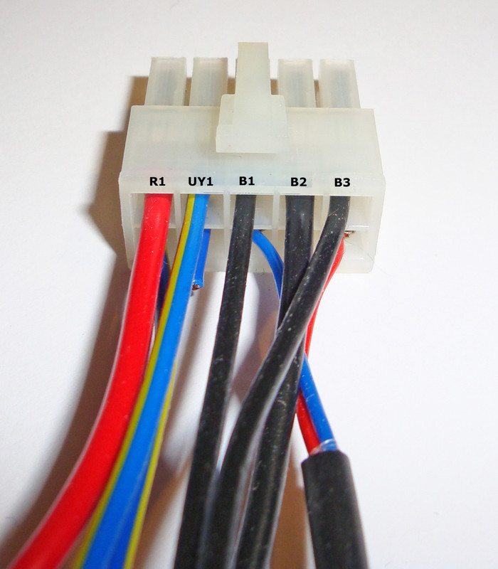
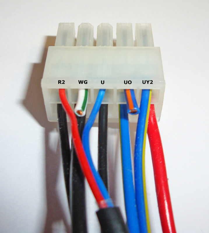
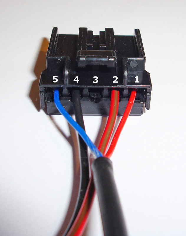
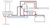
We'll start at the 10-way connector at the 'Control Unit'
Top row -
Cut
R1 - connect it to terminal 30 of your relay
Cut
B2 - connect it to terminal 85 of your relay
Cut
UY1 - we'll deal with this wire soon...
Cut
B1 and
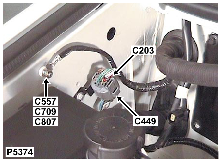
B3 - crimp them together in an M6 eyelet and take them to the earth point
C0557/
C0709/
C0807 on the inner wing -
The mounting bracket that the fuse holder clips to, can be removed from the 'Control Unit' body and mounted elsewhere.
It's held on by a small countersunk screw.
Bottom Row -
(ignore the fact that I've already cut the White/Green and Blue/Orange wires)
Cut
R2 and
UO - join them together (solder and sleeve, or splice joint)
Cut
U - connect it to terminal 86 of your relay
Cut
UY2 - connect it, with
UY1 from the top row, to terminal 87 of your relay
Cut
WG - NOT NEEDED - remove it back to it's 'tap-off' under the engine compartment fusebox, in a 'reverse' of the installation procedure, below -
Alternatively, you can just trace the White/Green wire
WG from the 10-way connector, back to where it emerges from the underbonnet fuse box Brown 3-way connector
C0572-1, cut it and tape-up the bare end.
Make sure that you don't cut the other
WG wire from the same terminal (
C0572-1), which goes to the inline White/Translucent cylinderical connector, as this powers a large number of ignition-switched circuits from the under-dash fuse box.
Changing the switch wiring to suit a PUMA Heated Seat Latching On/Off Switch (YUF500150LNF)
At the Black switch connector -
Open the hinged terminal lock and, using a safety pin from the front of the connector -
Release the Blue wire from cavity 5 and the Black wire from cavity 4
Swap their positions, so that the Blue wire is now in cavity 4 and the Black wire is now in Cavity 5
Close hinged terminal lock
Job done
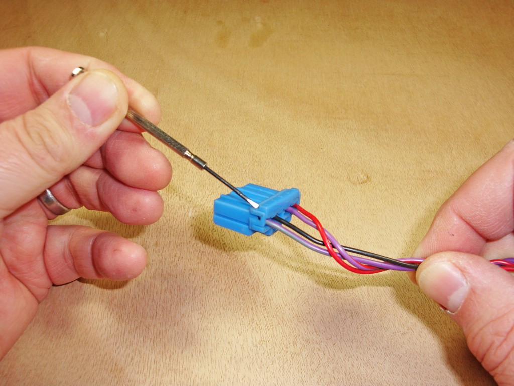
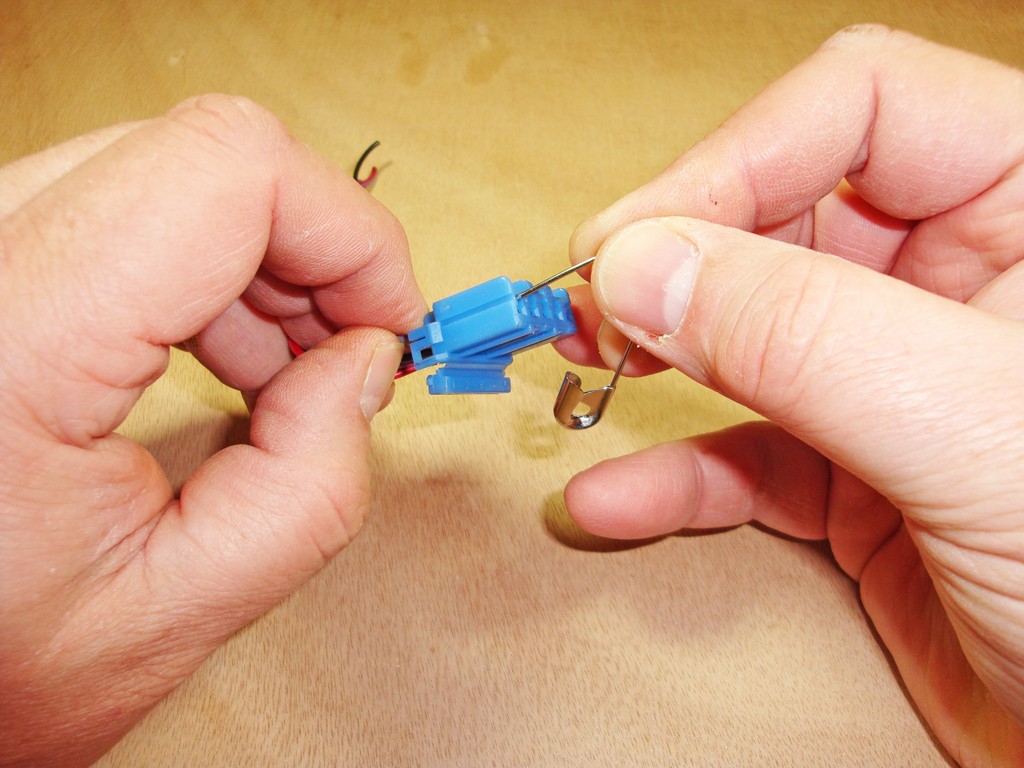
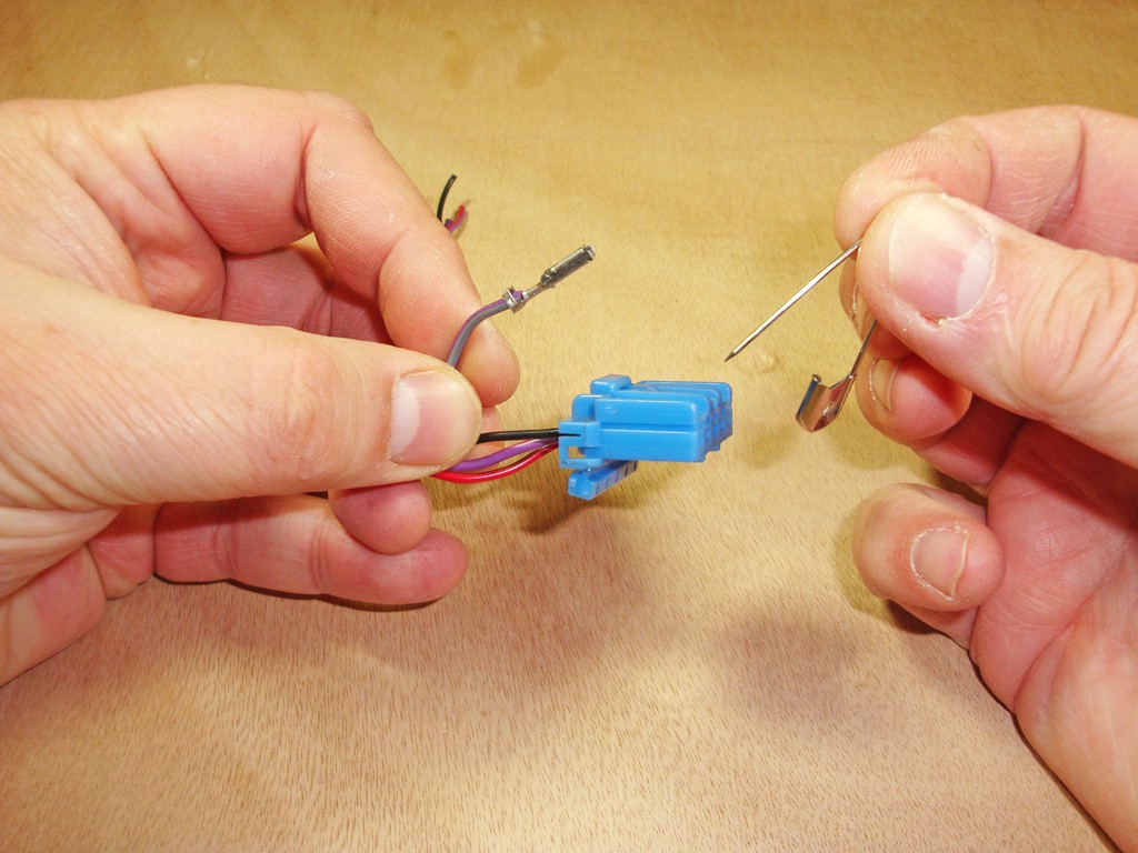
Here are some pictures that show how to open a 5-way switch connector and release the terminals.
These are from my '
Fuel Flap Relocation Harness'
Installation Instructions, so show a Blue connector, but the procedure is the same for all colours of these switch connectors -
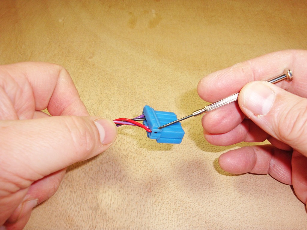
Use a small screwdriver to open the hinged terminal lock, 1st side -
And on the 2nd side -
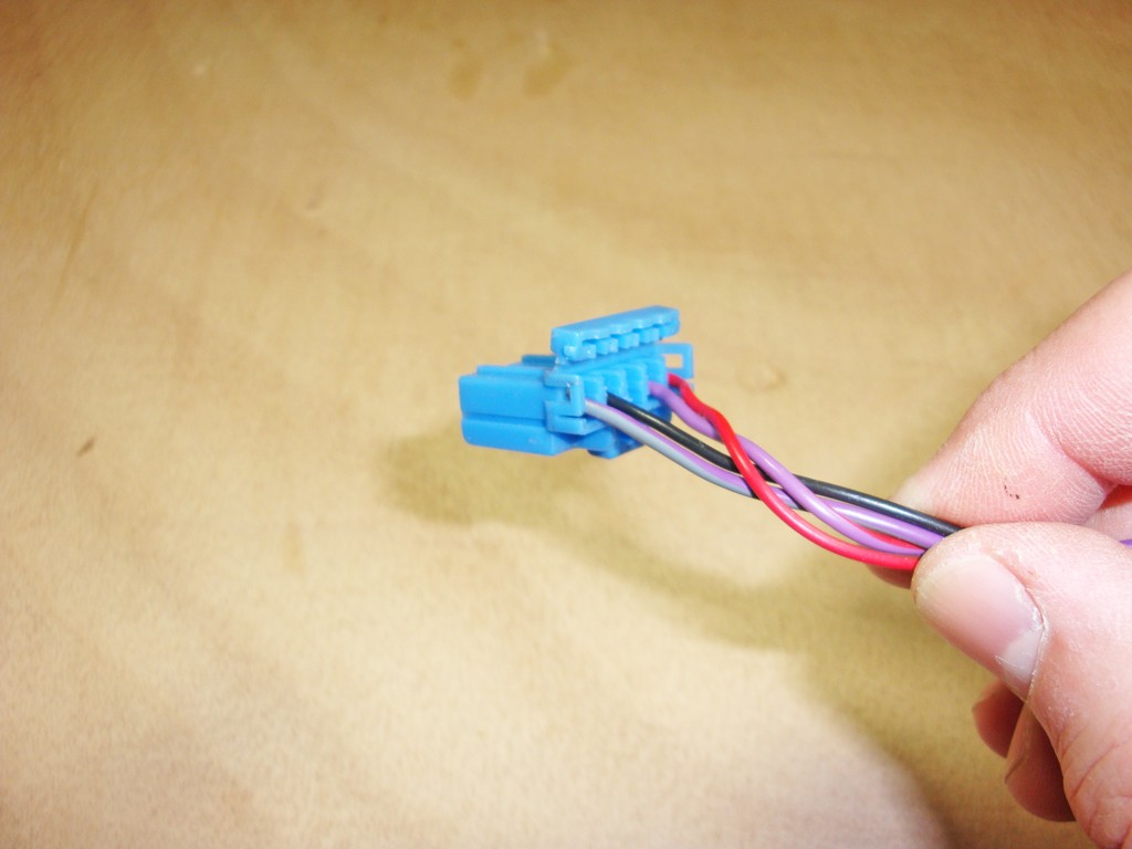
Hinged terminal lock opened -
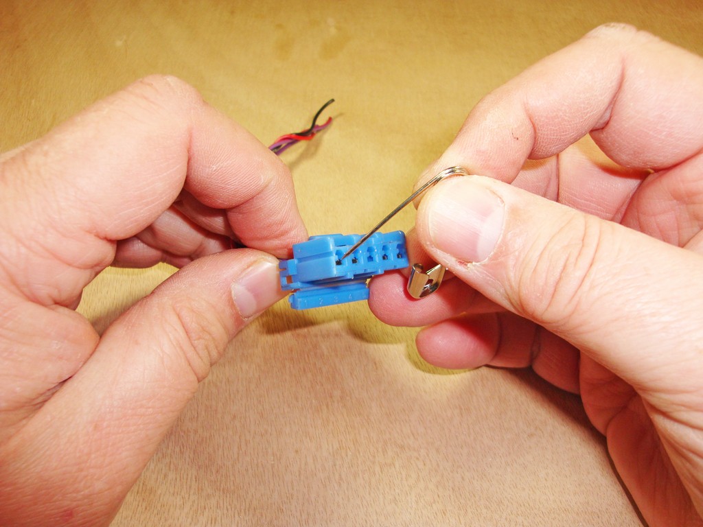
Use a safety pin to lift the locking tab above the wire's terminal -
At the same time as lifting the locking tab, pull gently on the wire
Terminal released from connector housing -
.