MG6 Turbo K series

This site contains affiliate links for which LandyZone may be compensated if you make a purchase.

DanielG

Member
Posts
29
Location
London
I’m in the process of swap my Freelander 1.8 k for the MG6 1.8T engine, there’s loads of little difference, nothing that can’t be overcomed by swapping bits of the old engine.

The only difference I’m worried about is that MG6’s crank sensor mount is 0.5cm thicker than the K series. Does anyone know if the sensor will still work correctly? It will effectively be 0.5cm further away from the flywheel.
 
I'd say that it won't work. Most rely on close proximity and designed to mate with engine design. You will need the original MG6 components and associated ecu or a new custom ecu.
Please document this transplant, very interested !! As will others be.
 
How are you going to control the turbo? Also, check the flywheel edge is the same as the 1.8k if trying to use the original sensor.
 
I’m using everything from a Rover 75 T. So I’m swapping to the 75T flywheel, turbo/manifold and 75T intake. Blank of the EGR on the MG6 version.

Then I can use the K Maps ECU I have. That’s the plan anyway, everything looks interchangeable but I won’t find out until tomorrow.

The plan for the sensor will be to cut off the mounting tag so the sensor can drop in further then cable tie it to the bolt.
 
The plan for the sensor will be to cut off the mounting tag so the sensor can drop in further then cable tie it to the bolt.

The distance from flywheel to sensor us critical. My view would be that a Freelander sensor held by cable tie with a Rover 75 flywheel would be a recipe for unreliable signals. Just a view. What do others think ?

As mentioned, please photo the transplant for the record.
 
The distance from flywheel to sensor us critical. My view would be that a Freelander sensor held by cable tie with a Rover 75 flywheel would be a recipe for unreliable signals. Just a view. What do others think ?

As mentioned, please photo the transplant for the record.

As long as the spacings correct and the sensors held firmly enough there shouldn’t be a problem.

But it all depends on what I find tomorrow, I will take some pictures and let you know how it goes fitting the SAIC engine.
 
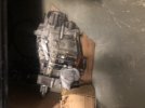
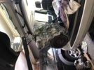
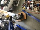
Evening, engines in and running here’s a bit of a write up about it.

When I say SAIC I mean the engine from the 2012 MG6

Differences that I could notice:

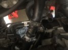
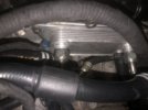
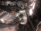
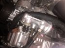
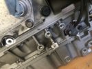
Oil Filter Housing (SAIC has 1 less sensor on it, fit 75/FL1.)

Block Coolant passage with coolant sensor (it’s the same as 75 so fit FL1.)

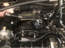
AC Pump - Pump Mount (AC pump sits to close on the SAIC, fit the pump mount from the 75/FL1)

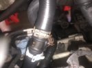
Crank Sensor Wing (0.5cm thicker and mounting hole in different place, cut .5 off the wing and drill and tap a new hole.)

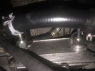
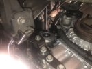
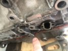
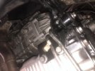
Sump casting (SAIC has a casting on the rear of the sump that allows something to mount, this fouls the IRD majorly and will not allow the engine to mount to the gearbox properly you need to cut a 1cm off.)

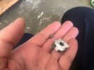
Cam Sensor (completely different, fit 75/FL1 sensor it’s a direct bolt on.)

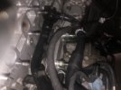
Intake (SAIC has electronic TB, fit 75 not FL1.)

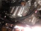
Exhaust I already had a new turbo so I fitted the 75 turbo and manifold. I had to remove 2 studs to allow the 75 manifold to fit.

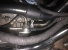
EGR (the SAIC has an EGR system which I completely removed and blanked, the FL1 doesn’t support EGR and I don’t see a way of incorporating it.)

Flywheel (Trigger pattern and type is different, fit FL1.)

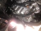
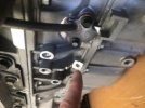
IRD 15mm bolt ( 3 bolts on the IRD are 15mm one of these doesn’t have an thread not a major issue just don’t fit one bolt.)

Engine Mount (SAIC has the same mount as the 75, fit FL1 mount.)

The SAIC is nearly identical with very few major changes. Unfortunately I don’t know how to add images but there’s not much to the mods I did, they were all pretty simple. Most problems could be fixed if you have a doner 75 engine.
 
Last edited:
Hi guys I just saw this now. I’ve also obtained an MG6 block and mated it to an FL1 cylinder head.
The way I overcame the sensor issue was by simply getting a bushing of same outer diameter with inner diameter matching the FL1 crank sensor and hammering it in to that hole, then simply drilling a new bolt hole then tapping it, once you’ve worked out the best place for the FL1 crank sensor tip to meet that groove or channel in the middle. I used Liquid cold weld sealant to plug up the old pre drilled hole for the MG6 sensor. What I did with mine was with my old block, I used a simple multimeter to measure the sensor resistances, then on the mg6 block when I had the bushing in place, I put the FL1 crank sensor in there and put on the FL1 flywheel and measured the same resistances to confirm a match. Other things I’ve encountered on the way - the IRD couldn’t fit until a shaved an approv 1cm tip off one point on the block. I also expanded a few of the holes for the FL1 sump bracket for it to fit in conjunction with the IRD bracket. I’ve also added the heat exchanger from the MGTF to use on mine, and am also going to be using the MG6 coolant reservoir.
 

Attachments

  • 777418BB-EC38-4410-8983-916D56FD0CF0.jpeg
    777418BB-EC38-4410-8983-916D56FD0CF0.jpeg
    21 KB · Views: 72
  • 6625FD52-10D6-43DF-A331-6058BBA576DE.jpeg
    6625FD52-10D6-43DF-A331-6058BBA576DE.jpeg
    29.7 KB · Views: 73
  • EEC967B1-B39E-4F36-9886-9AE8FF7298DF.jpeg
    EEC967B1-B39E-4F36-9886-9AE8FF7298DF.jpeg
    23.9 KB · Views: 63
  • 94E30AB1-CF5D-4DD3-A8BE-2AADEC77CA3F.jpeg
    94E30AB1-CF5D-4DD3-A8BE-2AADEC77CA3F.jpeg
    20.6 KB · Views: 79
  • A5D82E20-D44C-4E15-BE76-8A794EFB7ADC.jpeg
    A5D82E20-D44C-4E15-BE76-8A794EFB7ADC.jpeg
    23.3 KB · Views: 57
  • BCE4E570-FD88-4718-814A-319A4599901A.jpeg
    BCE4E570-FD88-4718-814A-319A4599901A.jpeg
    22 KB · Views: 61
  • 8210AC61-F0B0-4AB0-9A52-950482970B75.jpeg
    8210AC61-F0B0-4AB0-9A52-950482970B75.jpeg
    23.7 KB · Views: 68
  • D8FB8933-EE0B-4B44-AB5D-0FE409E28BC4.jpeg
    D8FB8933-EE0B-4B44-AB5D-0FE409E28BC4.jpeg
    25.5 KB · Views: 79
  • 4CC04E76-F1A1-4364-94E5-6DD7CD57ACD3.jpeg
    4CC04E76-F1A1-4364-94E5-6DD7CD57ACD3.jpeg
    26.2 KB · Views: 73
  • 9DBBC731-87DC-4C33-9E94-BDFDBB5195F8.jpeg
    9DBBC731-87DC-4C33-9E94-BDFDBB5195F8.jpeg
    26.4 KB · Views: 67
  • EF0ED1DC-3796-4861-83C5-14109D2F13DC.jpeg
    EF0ED1DC-3796-4861-83C5-14109D2F13DC.jpeg
    25.3 KB · Views: 72
  • 0E157935-38F0-4D65-97FB-F7DF90B7AA0D.jpeg
    0E157935-38F0-4D65-97FB-F7DF90B7AA0D.jpeg
    26.7 KB · Views: 63
  • 02C53EEE-7EEA-4FB2-A5F5-017F1370CEA2.jpeg
    02C53EEE-7EEA-4FB2-A5F5-017F1370CEA2.jpeg
    20 KB · Views: 79
  • 59440DD5-58F6-4488-B5A7-81E8F87654B7.jpeg
    59440DD5-58F6-4488-B5A7-81E8F87654B7.jpeg
    27.2 KB · Views: 74
  • 1903787A-7E33-4F2A-914B-5F873E0A26A5.jpeg
    1903787A-7E33-4F2A-914B-5F873E0A26A5.jpeg
    30.2 KB · Views: 72
  • 04512D7F-2FAF-40C2-B0E0-CA5C21CD070D.jpeg
    04512D7F-2FAF-40C2-B0E0-CA5C21CD070D.jpeg
    29.2 KB · Views: 63
  • 1DFC8B21-A539-469F-B228-CE2463F7BDAC.jpeg
    1DFC8B21-A539-469F-B228-CE2463F7BDAC.jpeg
    21.6 KB · Views: 64
  • 1A1AF353-982E-4662-A4A3-14EA195861AF.jpeg
    1A1AF353-982E-4662-A4A3-14EA195861AF.jpeg
    33 KB · Views: 62
  • FC3B4D1E-6B5E-4884-BEC9-EA05795A58FA.jpeg
    FC3B4D1E-6B5E-4884-BEC9-EA05795A58FA.jpeg
    35.3 KB · Views: 55
  • 18D86F10-DBD5-4E45-9647-61866A98D02F.jpeg
    18D86F10-DBD5-4E45-9647-61866A98D02F.jpeg
    27.4 KB · Views: 64
I missed this thread last time round, good luck with the build, it sounds very interesting.
There was a similar build thread with a MG75 1.8T a few years ago, TurboMike was the guy I think. If interested I can probably find it.
 
Found it
The member was called disco_mikey, not TurboMike. :rolleyes:
 
Back
Top