Diesel distributor pump filter

This site contains affiliate links for which LandyZone may be compensated if you make a purchase.

cheezels

Member
Posts
94
Location
Tewantin, Australia
I've been giving the Landie the once over and read somewhere that there is a filter on the inlet side of the distributor fuel pump.

So, I removed it to give it a clean and now I can't remember which way it goes back together :doh:

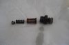
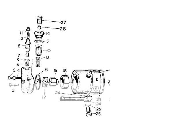
I will post a pic later of the bits that came out (filter, spring and what looks like a guide and summat else)........but in the mean time, does anyone have a drawing??

What a donkey!!
 
Injector pumps should be left as-is - fiddling with them is asking for trouble if you don't know what your doing....

NOTHING on this pump is easily adjustable, or serviceable without a LOT of ****ing about, or trashing settings / impeller blades.

If it works....leave it alone.

Here you go.
doh.jpg


Do a :search:eek:n here and you'll find a link to the Series parts and workshop manuals.
 
Hmmm thanks for the words of caution, but I'm only cleaning the filter, not resetting any timing or owt. Wasn't too hard to get out, and should have been easy to get back in if I hadn't fumbled the bits.

I've uploaded a picture of what I'm on about, as the drawing isn't too clear.

The piece on the left is what I can't remember which way goes round. I think the way it is in the photo is the way it should be.

Any thoughts?
 

Attachments

  • DSC00009.jpg
    DSC00009.jpg
    74.5 KB · Views: 496
Your photo is correct.

Diagram seems clear to me fella.
The "shorter" part of the regulating plug goes into the other spring....and the longer part goes into the spring in your photo.

edit: ** ....and your missing a washer ;) **
edit: ** ...taptalk is ****ing up again...took 3 edits to get this posted properly **
 
Last edited:
From the drawing I thought the longer bit of the plug (11) went into the spring (13). Is that what you mean??

You speak from experience, or just looking at the drawing?

Washer is in my parts tub ;)
 
Yup been there a few times.

You have the correct orientation.
Look at your pic, and then at your photo.

In your pic you have:
Items 11,13,10,14 (and the rest of the union)

Now look at the diagram - You'll see item 12 ( not in your photo) is both smaller and hopefully still in the regulator housing ;)

The filter unit you have there sits over the regulator assembly.
 
it may be drawn differently, but the assembly is the same.

The picture may be different in it's layout, but the assembly is identical if you look at the two diagrams they show the same components.


Here's a sectional drawing of the thing, showing its TWO modes, but what you need to see is which way up to fit the bits.

The engine should run even if the bits aren't in the right order, but starting from cold may be tricky.
 

Attachments

  • injpump2a.jpg
    injpump2a.jpg
    46 KB · Views: 384
Just to add to the last bit, the FIRST vital function of the pressure regulating valve is to enable you to BLEED and PRIME the injection pump.

If this valve is incorrectly assembled, there may be NO WAY to prime the pump because the only "way in" would be through the rotary vane intermediate pump inside the Injection pump proper. Fuel can NOT be pushed through that using lift pump pressure.

The thing on the end you took to bits allows Lift Pump pressure to raise the plunger enough to let fuel pass into the body of the injection pump, and flood it. The whole inner body of the Injection Pump should be completely filled with fuel. If it isn't, the engine may not fire up.

Here's a picture that tells the story. I hope it comes through big enough to read.
 

Attachments

  • injpump2b.jpg
    injpump2b.jpg
    81.7 KB · Views: 202
Here's a sectional drawing of the thing, showing its TWO modes, but what you need to see is which way up to fit the bits.

The engine should run even if the bits aren't in the right order, but starting from cold may be tricky.


Yes, I know it serves two purposes, but the assembly is the same in both exploded diagrams, quite clearly in fact.
I've already said the assembly is correct in the photo, so what's your point, CharlesY ?
 
Yes, I know it serves two purposes, but the assembly is the same in both exploded diagrams, quite clearly in fact.
I've already said the assembly is correct in the photo, so what's your point, CharlesY ?


The assembly condition is ABSOLUTELY NOT the same in the two diagrams that I sent, the ones side by side in the same pic.

The diagrams show fundamentally different conditions. Unless and until that can be seen and understood, there's nothing more to be said.

I am not making any point.
Someone had a problem, and I probably have the solution.
 
Thanks for all the help and advice.

I've put it back together, now, and only have the priming left to do. (see other thread).

Wish me luck.

Cheers


We wish you luck!
Remember to open the bleed valve on the pump before you start priming.

Before you attempt to start the engine, slacken off two (all 4 would be best) of the injector pipes at the injector end - half a turn is plenty.

Turn the engine over (or TOW it) till fuel appears in small spurts at the slack pipe unions. Tighten the injector unions, but not TOO tight.

It should be running very soon after this, as soon as enough fuel is shoved up the pipes to fill the injector passages.

Another way is simply to get a rope and tow it in 2nd or 3rd gear till its running. It won't take long.
 
Back
Top