Rear diff removal.
The rear diff on the FL2 isn't very difficult to remove.
There are several ways to do it, but I think the easiest way is to use the method I used, which will be detailed here.
First off, support the vehicle in the air on axle stands. I actually used 4 stands in total, a I hate getting under a vehicle unless its very securely supported.
I used 2 stands under the chassis rails, behind the rear wheels, and another 2 under the rear sill jacking points.
I used various bits of wood to adjust the stands, so all 4 got to share the weight of the vehicle.
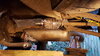
Once supported, I removed the rear wheels, to gain access to the suspension link bolts. I removed all 3 link bolts, which allows the rear hub to swing outwards, enabling the drive shaft CV joint to be released from the diff. The RHS (UK Driver's side) CV is easy to remove from the diff, requiring a large flat screwdriver, pry bar or even a car tyre lever, which is simply used as a lever between the CV joint and diff case. This pops the locking C ring, allowing the whole drive shaft to be withdrawn from the diff spline, as the hub assembly is pulled outwards.
I used a bungee strap to keep the shaft off the floor, and a plastic bag over the spline to keep it clean.
I repeated the procedure for the LHS (UK passenger side), although the CV joint is obscured by the diff casing extension, so a short stout screwdriver was used, the the access hole in the diff casing extension for this purpose.
Next is the propshaft to Haldex to flange bolts, of which there are 6 to remove. Each pair of bolts is passed through a curved washer, forming 3 groups of 2 bolts. This is the same design as the FL1 IRD to propshaft joint, and also the same as many other LR vehicles. The bolts are supposed to replaced on reassembly, so get some before starting work.
It should be noted, that the LR manual says these bolts need to be replaced, but I figure a dab of thread lock will do the trick, however I did replace them, as I know they'd been undone at least once before I got the vehicle.
I marked the propshaft relitive to the Haldex flange, so I could refit it in the same position it was removed from. As to whether this is necessary, I can't say, but that's what I did.
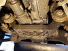
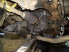
I found the easiest way to get the propshaft out the Haldex flange (it sticks quite tightly), was to free the front of the diff from its aluminium support, so it has some free space. To do this I removed the Haldex plug, then put a jack under the diff casing to take the weight. Next I removed the four 10mm head bolts from the underside of the support member.
I next removed the LH 18mm head bolt from the end of the support member, and released the RH bolt a couple of turns. This allows the support member to swing down and out the way.
With the support out the way, I lowered the jack a couple of inches (50mm), which would give sufficient room for the propshaft to be withdrawn from the Haldex flange. I then used a short stout chisel held at an angle on the propshaft coupling, and struck it with a hammer. It took a couple of firm taps, and the propshaft coupling popped out the Haldex flange.
Once the propshaft was free from the Haldex, I just let the propshaft hang, as it wasn't in the way.
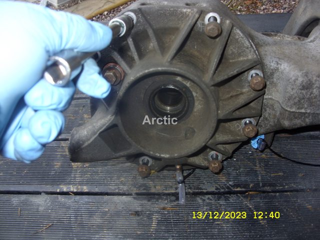
At this point there's only two more bolts to keeping the diff in car.
These bolts are accessible from exhaust side of the rear subframe, so require the rear box to be unhooked from its three rubber hangers. This job was made easy with a quick spray of silicone lubricant, after which the hangers can be slipped off the pegs with the aid of a screwdriver.
The exhaust can then be lowered to the floor, so access to the two 15 mm rear diff bolts can be made.
After the first bolt was out, I put a screwdriver in the bolt hole, simply to provide a bit of support, for when the final bolt was removed.
Once the last bolt was out, the only thing keeping the diff in place was the jack and the screwdriver. I then slowly lowered the jack about 4 inches (100mm) so I could get to the two breather pipes.
Once those are pulled off, the screwdriver was removed, so rear diff could be lowered to the ground. From there it was withdrawn out from behind the LH (UK passenger side) rear hub assembly.[/QUOTE
Hi Nodge,
I'm thinking of attempting this, a couple of questions
1. When removing the drive shaft from the diff does it just pop out ,apparently theres a clip around the shaft?
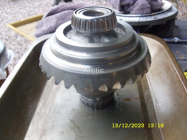
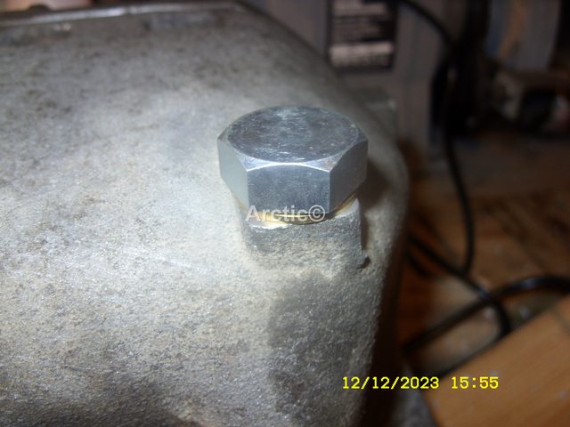
2. You mention a special tool to refit the bearing retainer nut, is this absolutely necessary?
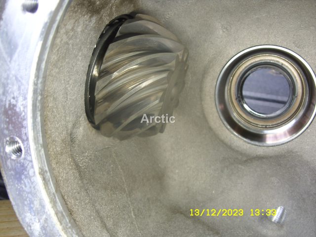
3.any recommendation on a good supplier of a reconditioned diff with upgraded nose bearings?
")