Series 3 109 Station Wagon, full ground up resto and 88 redo careless resto driving project

This site contains affiliate links for which LandyZone may be compensated if you make a purchase.
Thanks,
What a difference having argon shielding gas. Also so controllable.
I just wish my flanging tool worked on 2mm steel properly, but it's too thick. Because it would be great to ger that origonal flanged seam.
 
Modified my welding helmet with the addition of a LED Light
PXL_20210414_110517464.jpg

Sometimes welding into a dark corner, this should help me see what I'm doing
 
Thank you,
So I've been looking at how the origonal chassis is joined and welded
1618589608279185857429544754584.jpg
16185896686368746501806481545942.jpg

Not easy to split, night it is one continuous weld along the seam

16185898309983497161598128359184.jpg

With an overlap to the inside.
I have been trying flange tools to recreate this, but 2mm steel is proving a bit too thick so far, unless I put the flange jaws in a big vice which is not always practical
16185900873966477032350576832493.jpg

But does work sort of
16185903534323448509097950309745.jpg
 
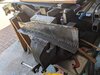
I'm rather disappointed to find my 2mm hot dip galv steel I bought from Barclay and Mathieson is not quite what is says it is

16188225799092816048900034761160.jpg

After countless measuring with my digital caliper, it measures as 1.8mm thick.
PXL_20210418_113854701.NIGHT.jpg

This is annoying but better to have been cautious and doing lots of measuring while near the start and while I can increase the thickness of what I have already fabricated to the inside.
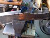
I was needing to plate inside the dumb irons after realising the origional leg continued inside, the dumb irons being welded on outside.


PXL_20210418_173357592.jpg


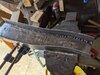
I had butt welded my outer chassis leg fabrication, then have been splitting and cleaning the old bits of leg out with an air finger file and chisel, to get a clean surface.
All this to preserve the origonal dumb irons with the chassis number stamped in.
I began to measure other parts like the new cross member and the origional chassis legs too.
I found the chassis legs are actually a bit thicker than 2mm!
My measurements varied between 2.2 and 2.3mm
PXL_20210418_173501639.jpg
PXL_20210418_173526172.jpg
PXL_20210418_173612137.jpg
PXL_20210418_173853500.PORTRAIT.jpg
It was quite interesting, but could my cheap digital caliper be inaccurate ?
So I tested them by measuring 5 sheets of 80 gsm standard printer paper. That should be 0.5mm and it was exactly that, so I measured 10 sheets, 15 sheets and 20 which should have been 2mm and it was accurate to 1/10th of a mm each time.
So I thought the Chassis rails were 2mm and the cross members 3mm. But on mine the Cassis rails are 2.3 mm and the cross members also 2.3 mm. Mounting points and various other bits like bump stops and their other welded on bits are generally 3mm.
So I have come to the conclusion that use of my 3mm sheet also bought from Barclay & Mathieson which as it happens measures as not 3 mm, but 2.8mm; is the way to go forwards.
By the time I have cleaned off the surface rust, fabricated parts, welded them in and cleaned the new metal up again. It will probably be more like 2.6 mm and only 0.3 mm thicker than the origonal metal.
Hopefully this will not cause any issues down the line being slightly stiffer and all.
Going to phone Barclay & Mathieson now and ask why 2mm is 1.8mm, interested to hear their excuse lol.
 
So apparently Galvanised steel has 'shot up' in price, and is very difficult to get hold of. But a 10 % tolerance in thickness is considered acceptable.
If my 2mm sheet is 1.8mm, I can't help wondering what it was before it was hot dipped, less than 1.8mm obviously ! Certainly not good enough fir me Landy.
The Chassis legs did measure 2.3, but I don't have a pic, the original cross member was actually 2.2mm
PXL_20210419_171144193.MP.jpg

Well that's enough footering aboot with all that. Time to get the dirty big sheet of 3mm (2.8) oot n'd get busy lol.
 
It's been too long, forgive me please.
Having to re-do what I had fabricated was a bit off putting but after having got some other projects out of the way I can confront re doing the front chassis legs again.
IMG-20210714-WA0002.jpeg

Plasma cut the four sides

PXL_20210715_144336183.jpg

Cleaned some surface rust off and fastened them together. Took many hours filing and grinding with flap disks to get them all the same and uniform and clean edges.
Cut the 1/2 width overlap parts, with the intention of ending up with an original join down the leg, like the lok of a woman's stocking leg lol.
Then clamped and tacked the parts together.
PXL_20210716_164508749.jpg

So the first 1/2 section replacement part looking like this
PXL_20210716_170238696.NIGHT.jpg
PXL_20210716_170306329.jpg
just loosely placed, but it gives an idea of how the two halves will go together, when finished, and then they can be welded down the overlap as originally done in the factory.
 
What a day lol.
So I tried making U sections to join
Taking my time to get them nice and straight[
PXL_20210717_090642399.jpg

PXL_20210717_092545518.jpg

But ran into a bit of a problem
PXL_20210717_095218130.jpg


Because they were never going to fit together as I was hoping they would, leaving a factory appearance.
So I dutifully took them apart again
PXL_20210717_164223786.jpg


Cutting all the track welds and prizing apart
PXL_20210717_170541269.jpg

Which left some deep gouges in the metal from the cutting wheel, which I fixed with some weld
PXL_20210717_173218654.jpg

And more grinding
PXL_20210717_173936916.jpg

So now I'll just do it like everybody else does, as a square section
PXL_20210717_174336864.jpg

With a top and bottom welded on.
I did however figure I could add a bead weld down the centre, which would replicate the original seam; It didn't feel right. But it was a day of experimentation.
I've had a bit of a break, because I got diagnosed with RA, which has slowed me down somewhat. But have a goal two complete the front part of the chassis, so it can be mounted onto my small metal box trailor and walked in and out of the garage as worked on.
My other two cars need servicing and MOT prepped. Having the use of my garage for other jobs aldo is a necessity.
Also if feels good to be getting some progress again after getting caught out with metal which was just too thin, so having to re-fabricate what has already been done.
But I'm just putting it all down to experience lol
 

Attachments

  • PXL_20210717_100257111.jpg
    PXL_20210717_100257111.jpg
    366.3 KB · Views: 60
  • PXL_20210717_164644650.jpg
    PXL_20210717_164644650.jpg
    320.7 KB · Views: 81
Sorry to hear of your diagnosis. Yes, sometimes doing things twice can be really frustrating, but at least you will end up with the result you want! I’ve had to do some jobs on my Landy more than once, but getting it right is more important .:)
 
Thanks GSF 109,
Once I find what works best for me to give a durable strong and aesthetically pleasing finish. I will be able to progress with a uniform system of fabrication.
Tomorrow I can make noise again and cut top and bottom plates, see how it comes together.
I recently picked up an even bigger bottle of argoshield light, and did a favour fir a neighbour welding up his metal trailor sides so he gave me heaps if 3mm long strips ideal for top and bottom chassis section fabrication. So I'm really looking forward to actually restoring some of my chassis, and not just going round in circles lol
 
That's 5 pieces of top and bottoms cut, although another cheap grinder died in the making.
1626704948747287121797296543753.jpg

RIP dead grinders.
16267050192934060971729257425808.jpg

Hello new slightly less cheap grinder from toolstation .
An I the only one who goes through a couple a year ? OK, so I'm using them most days but didn't they used to last longer?
So got five pieces ready to weld
16267052941004908769006776673531.jpg


Thinking of the best way to put the for parts together, was thinking with three parts they can be welded both inside and outside, the final piece closing the box off.

As in top right/ bottom left thinking sketch
16267054535826038742082766160773.jpg

Also a final bead could be welded along to replicate the original aesthetic
16267056361644946239196790212103.jpg

I'm overthinking this lol
 
I have just read all of your thread, your fabrication skills are very good. I am thinking of repairing my 1977 109 ex military chassis which only needs a few areas of rust cutting out, in fact the army’s under seal when chipped off reveals shiny black paint with clean metal underneath. But looking at the inside of your chassis I think I will get a camera inside to see what it looks like.
 
I have just read all of your thread, your fabrication skills are very good. I am thinking of repairing my 1977 109 ex military chassis which only needs a few areas of rust cutting out, in fact the army’s under seal when chipped off reveals shiny black paint with clean metal underneath. But looking at the inside of your chassis I think I will get a camera inside to see what it looks like.
Sounds like a good project, good luck.
Most of the Tibetan on my chassis seems to be where water has been trapped and sitting, muck build up and sits in some lower areas, even on top join difficult to access with the tub look places like Andover the front of the rear leaf springs mountings..
Hopefully, when I get the front the fabricated I can cut bad metal out and get a better view off what's going on inside.
When I removed the front cross member it was really bad where it joins to the chassis legs
16269807636628744832993114697311.jpg

From inside the chassis leg
1626980806297588859127379523017.jpg


And from inside the cross member.
Before cutting in, it was not possible to see this structural weakness, because of all the layers of plates that had been welded over.
I have a replacement cross member, that houses the dating relay, and would have been a bit more difficult for me to fabricate. But I'm fabricating my own chassis legs
PXL_20210719_151021135.jpg
and this time from 3mm steel
PXL_20210719_163318181.jpg

PXL_20210719_163550212.jpg
PXL_20210719_163558156.jpg
PXL_20210721_183552238.jpg
PXL_20210721_183609383.jpg

I ground the edge and welded the outside also, grinding to a curved edge too give the look of folded metal.
But there is no way I could fold 3mm plate.
For the top I came up with the idea of grinding back the corner edge to get really penetrative weld, and with the bead creating the curved edges.
Like in the sketch
PXL_20210722_174805153.jpg

PXL_20210722_171800899.jpg
PXL_20210722_172710669.jpg
PXL_20210722_173127310.jpg

I'll bring that smooth to look folded tomorrow
 
The welds are getting good penetration. Welding a corner of two 3mm plates had me concerned to get really good penetration
16270474490844852172888233528197.jpg

From the inside.
And outside
16270476344788139669121566362452.jpg
16270476748504871130309432328128.jpg


So that being strong, also speaks to my aesthetic self
16270478123318996564754378994157.jpg

Just one more deeds to do. Then It's time to get it in
16270480411357420648993034505206.jpg
 

Attachments

  • 16270478981116548752082566812063.jpg
    16270478981116548752082566812063.jpg
    321.5 KB · Views: 57
The front O/S outer Dumb iron/ Spring hanger has the chassis number stamped on it.
I was extremely careful to cover this number with some masking tape ages ago. In order to protect the faintly stamped chassis number, for the purposes of authenticity.
having removed it tonight to clean it up, I've discovered the masking tape has had it's own idea of where it should be and moved down .·´¯`(>▂<)´¯`·. c'est la vie!!
PXL_20210723_163552342.jpg


This caused some weld to pass over some details.

Previously I discovered the 3mm
galvanised steel I had bought from BM Steel Aberdeen was actually 2.6mm. I spoke with the manager - Gavin Morrison, who was really helpful and contacted the manufacturer to find that this is considered to be in range ?
But he did
offer to give me a good discount next time I'm by if I ask for him.
I only re-mention this to explain why I have cut away, welded and cut the chassis leg away from the front O/S outer Dumb iron twice. Because I'm having to make the leg again, with true 3mm steel, which I have measured other parts of the chassis legs to actually be.

This chassis is fighting me, and the temptation is to just get a new fully galv chassis, which would be a
sure-fire way to go, albeit quite expensive, but hey the responsibility for integrity would be not mine.

I'm so tempted to do this, fully treat wax and paint the outside with my Raptor U-Pol anti corrosive primer, then finish with a black urethane paint. Not getting any younger and this would allow me to get on with the fun stuff like rebuilding axles. Also it should easily last another fifty years or more.

I know I can do a great job of the chassis, but it will take a hell of a long time, especially due to having RA which
kind of pushes the button on a count down timer, and makes everything take longer because it effects the joints in finger's and thumbs, sometimes quite badly.

Just hate giving up on a chassis which with a couple of hundred hours could be rescued and
surpass requirement. ¯\_(ツ)_/¯

 
I reckon even with the RA you are doing better than I would expect to, Respect!:cool:
However I do understand the thoughts on new galv, I wish I had the time and space to consider rebuilding the original chassis on mine but thought it quicker and easier to just wait till I could afford to buy new so at least I can have it done while I am still fit enough to drive it.:eek:
 
Thanks Bruce,
Your too kind.
After looking at a photo of the dumb iron as it was, realized it was almost the same.
They corrode and get thinner in places, I cleaned off the corrosion from the back of the plate to see how much metal was left.
PXL_20210724_154226297.MP.jpg

Not really enough for a strong spring hanger. So they must be replaced, but after looking at what was available, decided the original's had bags more charm aboot em!

PXL_20210724_154217457.jpg


So I made a pattern of the original, using the near side also as a guide, because so many plates had been welded on that it was difficult to know where the top had been, so I made pattern
PXL_20210724_154020643.jpg


Also after looking at the insides, decided these were fairly corroded too. So made pattern for them as well, they are higher than the outer ones.
Taking note of the side profile for the double bend near the bottom
PXL_20210724_162823735.jpg

I measured the thickest metal at 4mm, I only have 3 so ordered some. The plasma cutter can cope with up to 1" so 4mm should be no problem, and I don't think forming the small bend will be a problem either, just got to allow a little extra material for that lost to distortion.
I like the shape of the originals, new replacement ones may be computer cut and super accurate, but I've deliberately exaggerated the organic curves below the extra holes at the bottom from the original ones.

Does anybody know what the extra double and single holes are for please? There must be some purpose, and they're a factory finish, maybe to attach something!
 
The two smaller holes are for the optional steering damper, fitted to V8 and six pot versions.
Not sure about the single one.
 
Back
Top