Series 3 Accelerator controls for NA 2.25 diesel

This site contains affiliate links for which LandyZone may be compensated if you make a purchase.

Jules59

Member
Posts
45
Location
Warwickshire
Hi
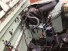
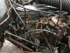
Im trying to work out how to refit the accelerator cable and rod linkages to the 10J NA diesel. Also the engine stop.
Long story short - Ive taken over an abandoned project where the engine had been removed and the controls. I cant find any pics/diagrams of the accelerator controls for this particular setup and how the short cable connects via rods and shafts from the lever on the pump to the peddle (certainly not in my Haynes manual).
Could someone send me a link or some pics please.
 
S3 (44)b.jpg

Where does cable anchor bracket 598851 usually attach to the bulkhead ?
Anyone got a pic showing where it goes ?
 
Last edited:
That would be most helpful - thank you.
Out of interest can I ask why you removed the engine?

I'm working on the brakes at the moment. A previous owner had installed twin cylinder 11" front hubs onto to this SWB S3 and the lower cylinders on both sides had seized. They are awkward to bleed too.
 
I’m putting in a 200di, while it’s out I’m going to tidy up and paint , those brakes are standard on later series 3 , I have them on my 84 diesel, if you’re changing them I would get some Lucas TRW makes the last a bit longer , a lot of people have trouble bleeding the twin leading brakes , there’s lots of threads if you search some even take the brake back disc off and bleed horizontally, never found that necessary, I use an easibleed type kit from Halfords less than. A tenner one man and can’t fault it
 
I had a Gunson Eezibleed that used tyre pressure to pump brake fluid through the lines but after 20 years of use it started to leak. A new one is £20 these days.
 
Nice looking Landy , seen the pics on your intro, some pics of empty engine bay , the bracket is fixed t bottom of fuel injection pump , I might have som either pics of engine bay before took engine out , on the camera so will need to connect to puter.
2EA25A72-CCBC-49ED-AAD5-D979D0F49BD9.jpeg F92471E7-4E2C-48C4-9050-86C2B111BE03.jpeg F92471E7-4E2C-48C4-9050-86C2B111BE03.jpeg
318175A0-40BA-49BD-A5DA-9CFD2DA2E8F7.jpeg
 

Attachments

  • E0906A88-52FE-4162-837C-C245C3923A3F.jpeg
    E0906A88-52FE-4162-837C-C245C3923A3F.jpeg
    290.8 KB · Views: 426
Thanks, more pics of the bulkhead would be great. It seems to be a slightly odd setup in that the cable pulls up the accelerator arm on the pump by having the other cable end fixed to the bulkhead and the cross shaft arm pushing on the outer sleeve which in effect pulls the cable up. I've got the cable attached to the injector pump and the outer sleeve anchored at the injection pump end. Im just trying to see where the is best place to anchor the cable end to the bulkhead.
 
I think 90577499 goes onto lever of rod system and the other bracket bolts to bulkhead possibly on cross shaft anchorage.
system is odd in the way both ends of cable are anchored and the sleeve moves to operate the linkage,
Found this pic but still not obvious
 

Attachments

  • 2.25 diesel.jpg
    2.25 diesel.jpg
    462.4 KB · Views: 255
Last edited:
Thanks Steve, Ive got that diagram too. But its nothing like the set up Ive got. Mine is like the photo from Blackburn. Mine uses one connecting rod, one spring, one cable and (I realise from the photo) the actuating arm on the cross shaft has to be hanging down below the cross shaft so that it moves forward & upward when the accelerator peddle is depressed. Sticking upright as in the diagram simply wont work.
 
After a bit of trial and error Ive got the accelerator cable working. I had to make the bulkhead bracket for the cable end anchor point. You can see how it works below...
S3 (50) (Large).jpg

S3 (51) (Large).jpg
 
Back
Top