Heater switch wiring query.

This site contains affiliate links for which LandyZone may be compensated if you make a purchase.

westone

Active Member
Posts
415
Location
West country
Hello all,
firstly thank you all who have helped during my first 5 weeks of Series 3 ownership, been very much appreciated.

I am now trying to wire in my heater switch on the dashboard and have come to a dead end.
I have bought a new switch but cannot get it to work.Same a the original one.

I have tested the bower by connecting up a battery to the wires which go to the blower feed wire and have both speeds,I swoped over the wires from one to another.

But the switch I am in disappear with it as do not have any volts?

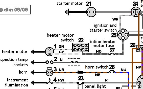
It is wired like this brown/orange wire connected to T3.Green/yellow to terminal 6,Brown/green to terminal 7 and green/silver to terminal 8.

The blower wires are the ones on terminal 6 and terminal 8.

I do not understand what the other two do,I assume one should be a power feed?,but I do not have any power.A brown/orange wire with a fuse is under the dash and is connected to the one on the switch,I checked this with my meter on Ohm setting.But when i connect a battery i get sparks?
I have a copy of the light weight series 3 wiring diagram but cannot work out what terminals go to with connections on the switch.

I did read on the forum that the brown/green on T6 is a power feed as well which has confused me.?
I thought I should just have 3 wires on the switch, but not sure which 3.
I did think if i disconnected T3 and T7 and then took a new wire from the fuse box with an inline fuse that might work, but which terminal do i connect it too please?
I would appreciate any guidance.
thank you.
 
47901746511_23f037f826_z.jpg


1 Blower
22 Blower Switch
27 In-line Fuse

GN GreenBrown
GY GreenYellow
NO BrownOrange

Just done a few experiments and this is what I got.....
Terminal 4 Feed to the switch BrownOrange
Terminal 6 Lights up in Mid Position
Terminal 8 Lights up in Down Position

So I think 6, GreenYellow, should go to the slow speed, with 'resistor'? and 8, GreenBrown goes straight through and gives Hi speed.....
 
Last edited:
Check the fuse - it may be somewhere unexpected, it may have blown during the swap if 2 wires touched.. Check how the resistor is wired, they can be hard to find and in my experince are often connected wrong. Can you put it back exactly as it was and does it work then?
 
Thanks David for doing that for me i have printed your answer out and i will re wire it.I noticed tonight 3 wires are in a small harness and the other one the Brown/green is not just comes from the loom,
I will follow your connections,I also noticed the ignition switch is full up no spare connections so will get a double connector for it.

Thank you Rob i have checked this and its okay its a 25amp fuse.
 
You don't need the brown/green wire for the heater fan circuit. The wiring diagram for the Lightweight (the one in David's post) has two brown/green wires: one for the brake light switch and one for the hazard switch, so if you have a spare brown/green wire, it may be that either your brake lights or hazard lights don't work!
As Rob said, it's possible the fast/slow wires on the fan are wrong, but that's not a big deal - if the fan runs at full speed on both settings, just swap the green/brown and green/yellow wires on the switch.
The military electrics on Series Landies are a bit different and sometimes get bodged by owners who want to bypass the infra-red (blackout) lighting system. There's lots of useful information on the Lightweight site: http://www.land-rover-lightweight.co.uk/
 
Thank you for your posting,I will tape of this wire, my brake lights work and i do not have any hazard lights.I am hoping it will finally work.
 
I have the flat heater as mine is an S2A, but what fooled me was that the 2 speed resistor was inside the heater. 2 wires went into the heater and 2 came out and went to the motor so I wrongly assumed they were the same wires. Actually the motor was earthed inside the heater and the 2 wires going in were fast and slow.
 
Thank you Rob,
Well please to report all fixed and working I followed David's diagram and found a live feed on the ignition from a large white wire,I used a dual connector as the switch did not have any spare spades. Now it rumbles away.I did not work at all when i got the wagon.
The other wire brown and green is taped up.

Thank you all for your help.
 
Thanks all for this -
I have a 1970 Series IIA, and have not yet tackled this issue.I did notice over the winter that the blower motor seemed to have only one speed (very slow) regardless of whether switch was in middle position or full on. So this all is helpful.
David - I liked that wiring diagram, and can you please tell me where I can got a copy? The ones I have are from the manuals and they differ somewhat, and are a bit hard to read on account of the small print.
About the blower motor - can I assume that this does have two speeds? Or do some blower motors have only one speed?
Thanks!
Mike
 
Mike, the fan motor itself has one speed. The second (slow) speed comes from feeding power to the motor through a resistor. If you have only slow speed working, it may be a faulty switch, or a wiring problem like westone had. IF you only have fast speed, the resistor may be faulty.
Note that the wiring diagram above is the military version - it's not exactly the same as the civilian Landy, the differences are mostly in the lighting circuits.
 
In case it helps my unit blower was completely damaged when i got my wagon and the heater housing was not a lot better.So i looked around for a replacement and read that the original unit was poor at heating the cab so bought a 12v bilge blower from e bay at £16.95 post paid.I read about a chap who had done this on line.(SEAFLO IN LINE BLOWER 12V 3" MARINE BOAT VENTILATION in-line air vent inline) Thats the spec.

As I did not have a resistor I bought two 1.5Ohm 50 watt units( 1.5 Ohm Golden Aluminium Load Resistor Wirewound ) thats the spec and they cost £2.89.By using these it reduces one of the two wire feeds to the blower by 3volts.so gives the slower speed.The other wire feed gives the high speed.
If you need a resistor one of these would do it and you get two for £2.89 arrived in 2 days.

Now all working after Davids excellent diagram.

I had to cut a 5inch hole in my wing as it did not have one, found this hard and worrying, but did it okay and an original unit could be fitted if required in the future.
 
Guys -
Thanks for all the info and especially the chart. It will be helpful, for sure. I've noted the resistor type in case I need one.
Thanks again,
Mike
 
To follow on from this I removed the lower dash as the heating control lever was very stiff and was shocked at what i found, please see picture below.The top part with the holes in for the windscreen tubes was just filler(the white area) and coming apart,corners the same and the rod for the flaps had corroded free of any mountings on the dash, this area was just solid rust and could be holed by light pressure.

So I think i need to get a replacement if possible, Does anyone know if they are made please as a part or any other suggestions would be helpful?
I looked at a couple of used ones on ebay and was shocked how much they were asking for them.I cannot afford those prices,

I think i can see now why the previous owner did not bother to fix the heater switch and blower..

.All I can think to do is make up a metal box and cover the heater blower inlet to the cab and run windscreen tubes from this.
Thank you gents.
IMG_3881.JPG
IMG_3878.JPG
[
 
Last edited:
Back
Top