You are using an out of date browser. It may not display this or other websites correctly.
You should upgrade or use an alternative browser.
You should upgrade or use an alternative browser.
6-Wheel Drive Discovery II - Am I totally mad ?
- Thread starter dave658
- Start date
This site contains affiliate links for which LandyZone may be compensated if you make a purchase.
- Posts
- 9,105
- Location
- Roaming the UK on assignments
Dave, you're keeping us all on tenderhooks; how did the testing go and what about a few cockpit and engine bay porno pix?")
He thinks we're all cross dressers and wants us in suspenders not suspense
I'm trying not to hassle him about it but really want to know how it got on myself.
dave658
Well-Known Member
- Posts
- 118
- Location
- Yateley, Hampshire
Dave, you're keeping us all on tenderhooks; how did the testing go and what about a few cockpit and engine bay porno pix?
Hi guys, sorry for the delay - the bad news is it did NOT pass it's electrical safety test. It failed on cable routing and colour coding. They were not happy with the spacing of the cable clamps, the way they passed through the body shell (they suggest they may be subject to chaffing, and at 600V, that would be bad !) and the colours have to be orange to indicate 600V. I have green, yellow and blue cables for the 3 phases of the motor with an orange band on either end to indicate the high voltage, but no - apparently the cables all have to be solid orange all the way along - I pointed out this was silly as it then wasn't possible to identify the phases, but regulations is regulations ! MY new plan is to use a 3 way EV connector to lock the phases in place
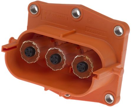
but getting access to all this and sorting out the clamps is a pain as they run between the body and the chassis.
So I have taken the plunge and decided to lift the bodyshell off and do it properly, it's a major pain in the a*** and will add significant time to the development, but I will also improve cable routing of other looms and the brake pipes etc while it's off and it's an opportunity to really treat the chassis and bodyshell to some rust protection while they're apart, it will be a great opportunity to do these jobs right and to get some great photos of the engine, transmission and electric drive trains, so not all bad
Magicgrotto
Well-Known Member
- Posts
- 2,769
- Location
- doncaster
F000000000KIN JOBS WORTH'S 1988smithy
Well-Known Member
- Posts
- 3,897
- Location
- West midlands
Fair play for seeing the positives and doing the job right
- Posts
- 15,138
- Location
- Benfleet, Essex
Sorry to hear their decision, but full marks for making the best of it!
Sorry to hear their decision, but full marks for making the best of it!
Agree...but looking at the build would'nt expect anything else from him...
caretaker87
New Member
- Posts
- 3
- Location
- sheffield
this is a fantastic build, i wish you the best of luck with it, if i may make a suggestion could you use coloured heat shrink at the terminations to identify each cable and thus the phases? i take it this would be acceptable now as you're re routing the cables and replacing them with all orange cable, failing the coloured heat shrink could you use cable identification numbers, you can get them in selves that fit over the cables or in a sleeve that can be zip tied to the cable. i can't wait to see this finished but i do have a question, if for instance you're in 6x6 will you match the rear electric motor to the petrol engine via wheels speed or engine revs or some sort of torque calculation? i have no idea which is best or if it makes any difference i am just generally curious.best of luck.Hi guys, sorry for the delay - the bad news is it did NOT pass it's electrical safety test. It failed on cable routing and colour coding. They were not happy with the spacing of the cable clamps, the way they passed through the body shell (they suggest they may be subject to chaffing, and at 600V, that would be bad !) and the colours have to be orange to indicate 600V. I have green, yellow and blue cables for the 3 phases of the motor with an orange band on either end to indicate the high voltage, but no - apparently the cables all have to be solid orange all the way along - I pointed out this was silly as it then wasn't possible to identify the phases, but regulations is regulations ! MY new plan is to use a 3 way EV connector to lock the phases in place
but getting access to all this and sorting out the clamps is a pain as they run between the body and the chassis.
So I have taken the plunge and decided to lift the bodyshell off and do it properly, it's a major pain in the a*** and will add significant time to the development, but I will also improve cable routing of other looms and the brake pipes etc while it's off and it's an opportunity to really treat the chassis and bodyshell to some rust protection while they're apart, it will be a great opportunity to do these jobs right and to get some great photos of the engine, transmission and electric drive trains, so not all bad
this is a fantastic build, i wish you the best of luck with it, if i may make a suggestion could you use coloured heat shrink at the terminations to identify each cable and thus the phases? i take it this would be acceptable now as you're re routing the cables and replacing them with all orange cable, failing the coloured heat shrink could you use cable identification numbers, you can get them in selves that fit over the cables or in a sleeve that can be zip tied to the cable. i can't wait to see this finished but i do have a question, if for instance you're in 6x6 will you match the rear electric motor to the petrol engine via wheels speed or engine revs or some sort of torque calculation? i have no idea which is best or if it makes any difference i am just generally curious.best of luck.
I think if you have read this build from the start your thoughts are like trying to teach someone how to suck eggs...he has informed us the result of the inspection and the way to resolve it with upgrades to his standards...
caretaker87
New Member
- Posts
- 3
- Location
- sheffield
well id hope it didn't offend him but sometimes the easiest solutions can be overlooked, from my line of teaching there are no stupid questions '' some cable identification for fault finding reasons may be beneficial, if the op is on this train of thought the brilliant, the aim of my post was to help, what was yours?I think if you have read this build from the start your thoughts are like trying to teach someone how to suck eggs...he has informed us the result of the inspection and the way to resolve it with upgrades to his standards...
dave658
Well-Known Member
- Posts
- 118
- Location
- Yateley, Hampshire
this is a fantastic build, i wish you the best of luck with it, if i may make a suggestion could you use coloured heat shrink at the terminations to identify each cable and thus the phases? i take it this would be acceptable now as you're re routing the cables and replacing them with all orange cable, failing the coloured heat shrink could you use cable identification numbers, you can get them in selves that fit over the cables or in a sleeve that can be zip tied to the cable.
Yes that's pretty much what I envisaged. I had that arrangement previously with orange sleeves over either end of my phase coloured cables, but given the (stupid) requirement that the cables all be orange, I will use phase coloured sleeving at either end to identify which phase is which. It is really important to know which cable is which phase. For diagnostics, I use three hall-effect clamps (you can get away with two and imply the third), but if you don't know which clamp is on which phase, then it is very hard to correlate your results.
i can't wait to see this finished but i do have a question, if for instance you're in 6x6 will you match the rear electric motor to the petrol engine via wheels speed or engine revs or some sort of torque calculation? i have no idea which is best or if it makes any difference i am just generally curious.best of luck.
That is actually an extraordinarily insightful question and the answer is complex, and not yet fully implemented. The simple answer is the electric motor is speed matched to the petrol drive-train speed as measured at the transfer box, but in reality, the motor runs a little faster than the petrol in over-run and a little slower in under-run subject to traction control limits. This gives maximum use of the huge torque reserved of the electric motor while accelerating whilst adding improved stability during deceleration. This is further complicated by whether or not regenerative braking is enabled (this is currently an on or off setting, but will, at some time in the future, have options for different levels of regen)
The real fun comes in the transitions from petrol only (4wd), to electric only (2wd) or both (6wd) and vice-versa. When engaging the electric motor, the motor speed is electronically matched to the petrol drive train very precisely before the dog clutch is engaged which puts us into 6wd. The transfer box can then be moved to neutral if we want to switch to electric only at which point the engine can be dropped to idle or even switched off. This transition currently works very well and the take up is very smooth. To go the other way, The engine is started, brought up to the correct speed with an appropriate gear selected, then the transfer box dropped into high range to engage the drive. The motor can then be disengaged, driven or used for regen as necessary. Testing of this transition so far shows that there a major "clunk" during take up, which is uncomfortable and not at all good for the mechanics, a problem I will need to resolve.
I think the issue is that it is possible to control the speed of the electric motor much more precisely than it is for the engine/gearbox/transfer-box combination, and I think it is that mis-match that results in the rough take-up. I think I will need to fine-adjust the motor speed to actual transfer box speed before moving to high-range to better control this transition, but hey - teething troubles (no pun intended
)well id hope it didn't offend him but sometimes the easiest solutions can be overlooked, from my line of teaching there are no stupid questions '' some cable identification for fault finding reasons may be beneficial, if the op is on this train of thought the brilliant, the aim of my post was to help, what was yours?
To point out he had already mentioned cable identification in his post allthough different to the way they require and to my mind his system is better,your reply gave the impression you hadn't read it,he is a superb builder of a unique vehicle and attention to detail second to none in my opinion especially when electrics are involved.
dave658
Well-Known Member
- Posts
- 118
- Location
- Yateley, Hampshire
To point out he had already mentioned cable identification in his post allthough different to the way they require and to my mind his system is better,your reply gave the impression you hadn't read it,he is a superb builder of a unique vehicle and attention to detail second to none in my opinion especially when electrics are involved.
Well I appreciate the support, but I took the question in the spirit it was intended
NRS91
Active Member
- Posts
- 189
- Location
- Macclesfield, UK
Have you got an output shaft speed sensor on the auto box?
Shifting a transfer box is like shifting a crash gearbox in an old wagon, in this case the driver will normally overshoot the required engine rpm a little then engage the gear as as the engine rpm drops to the correct speed to slot the gear in cleanly before reapplying power.
This means there is only inertia and not actual power going through the drivetrain when you engage the next gear which will reduce or eliminate any clunking.
Maybe if you can program this control logic into the shifting logic and account for the speed of the high range actuator you will get rid of the clunking?
Though a lighter vehicle will be more susceptible to clunks than a laden one.
LincolnSteve
Well-Known Member
- Posts
- 1,184
- Location
- Lincoln
I realise that i'm not the first person who has said this but this build is incredible!
@dave658 your knowledge and skill is an absolute joy to see and as for the way you are able to deal with the set backs along the way you are inspiring.
Keep going and treat yourself to a chocolate hobnob or something because you deserve it.
Steve.
@dave658 your knowledge and skill is an absolute joy to see and as for the way you are able to deal with the set backs along the way you are inspiring.
Keep going and treat yourself to a chocolate hobnob or something because you deserve it.
Steve.
- Posts
- 9,105
- Location
- Roaming the UK on assignments
Who's is that?
Smashing 300Tdi D1
Knupke
Member
- Posts
- 40
- Location
- Huissen The Netherlands
great build with a lot of nice electronics work done i'am a petrolhead by birth but this is incredible
keep up the work and don't let them get under your skin
keep up the work and don't let them get under your skin
- Posts
- 9,105
- Location
- Roaming the UK on assignments
@dave658 Hi, any update on the project? Tnx
He's forgot about us, I was sure he could have had it booked in and retested again by now?
Similar threads
- Replies
- 6
- Views
- 705
- Replies
- 0
- Views
- 168