Defender 90 300Tdi Engine Rebuild

This site contains affiliate links for which LandyZone may be compensated if you make a purchase.

wvanzyl

Member
Posts
44
Location
Cape Town, South Africa
Hi All,
After having owned my Defender for roughly a year and a half the time has arrived for me to rebuild the engine. She has done 206 000km, not a heck of a lot considering it is a `96 model.
attachment.php


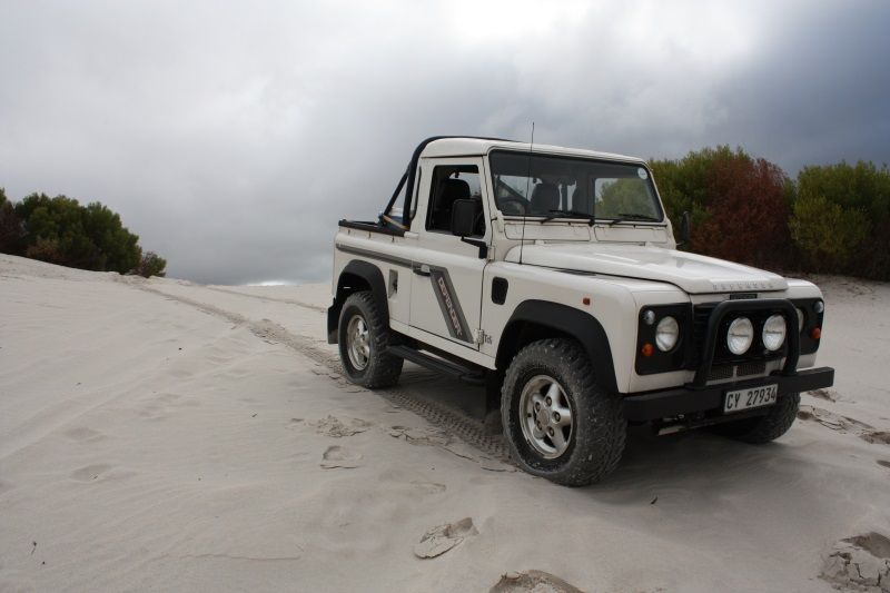
I previously owned a 2006 Defender 90 Limited Black Td5, what a nice car that was! Sadly I had an itch and sold the Td5 :confused:.
I longed for a Defender and stumbled across this one. Work done since I bought her includes wheel bearings and seals replaced, stub axles reconditioned, swivel pins rebuild, new cv's, rebuild both doors (mainly just to clean them out) rebuild the transfer box, replaced rear crank oil seal, rebuild the injector pump and got injectors tested, rebuild the turbo and fitted a new timing belt, it also had a good service.
Apart from the seats requiring new foam the engine is the last big ticket item to be sorted, then my Defender will be better than new. I did not plan to redo the engine now but she is using oil and it's not nice driving your Defender when you know something is not right. I believe the engine, as with the injector pump and turbo, is warn because of the high sulphur/sand/whatnot content of the diesel it was ran on known locally as farm diesel, or.....diesel of death if you ask me, and the lack of maintenance or oil services.
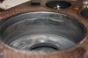
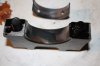
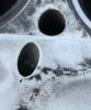
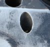
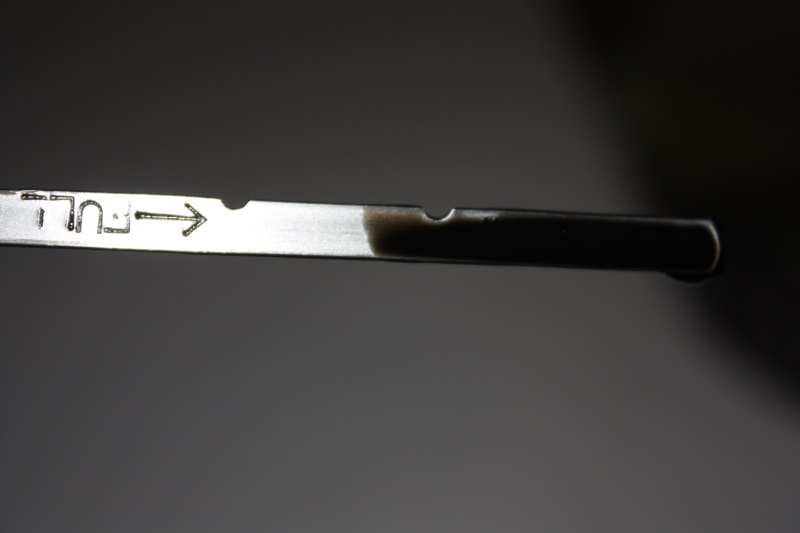
I've done about 1500km - 2000km since the last service and look at the oil level below!
attachment.php


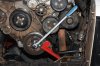
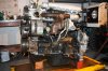
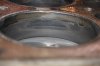
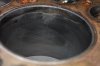
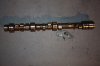
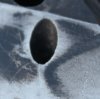
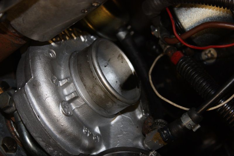
The oil usage is attributed to sump back pressure. At higher revs oil gets pushed up past the cyclonic breather into the turbo inlet as can be seen below
attachment.php


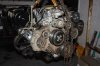
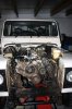
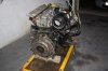
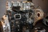
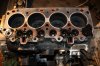
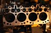
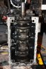
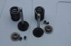
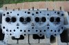
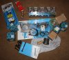
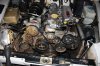
So, strip down has begun. I've totalled roughly an hour last night to get to this stage
attachment.php


It doesn't look like much but the starter is off, radiator removed, oil and water drained and most the pipes are out of the way.

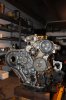
Next I need to drain the PAS pump oil and also need to decide how I'm going to handle the aircon pump, probably best to remove it so it's not in the way when lifting the engine out.

Till next time.
Willie
 

Attachments

  • Dunes.jpg
    Dunes.jpg
    46.4 KB · Views: 1,556
  • Dipstick.jpg
    Dipstick.jpg
    44.1 KB · Views: 1,107
  • Turbo.jpg
    Turbo.jpg
    55 KB · Views: 1,238
  • Day1Progress.jpg
    Day1Progress.jpg
    89.6 KB · Views: 7,070
Last edited:
After a very busy weekend I found time yesterday afternoon to finally remove the engine.
What I find puzzling is some of that sand (See very first picture on page 1) somehow made its way into the bell housing. I played in that sand for 6 hours, the wade plug was/still is fitted to the bell housing and as far as I'm concerned there is no other hole where sand could have entered. I am puzzled as to how sand made its way into the bell housing but will try to figure that one out.....
attachment.php


After having disconnected all the air, fuel and oil lines I disconnected all electrical connections and continued to removed the aircon pump and radiator.
Before I could remove the engine I had to manufacture a bracket to bolt to the rear of the head to be used in conjunction with the lifting point bolted to the front of the head, nothing fancy.
attachment.php


Before going any further it is wise to first undo the crankshaft pulley bolt. This thing is tight and it will be a hassle to undo on the workshop floor when you would need to hold the engine steady whilst trying to undo the bolt.
attachment.php


Next up I hooked the engine to a hoist and gently lifted it out of the engine bay. One thing I would have done differently would be to unbolt the exhaust downpipe from the front of the first silencer underneath the car. I only unbolted it at the exhaust manifold which made it difficult to manoeuvre the engine away from the car as the flange was constantly preventing me from getting the engine out. Have I lifted the engine higher this probably would not have been an issue.
attachment.php


The engine is now resting on a trolley. From here I will start the strip down but I will first pressure wash it so that it is nice and 'clean'.
attachment.php


Till next time.

Willie
 

Attachments

  • Bracket.jpg
    Bracket.jpg
    41.2 KB · Views: 981
  • Crank Bolt.jpg
    Crank Bolt.jpg
    81.1 KB · Views: 1,165
  • Engine Hanging.jpg
    Engine Hanging.jpg
    65.4 KB · Views: 1,126
  • Aircon Removed.jpg
    Aircon Removed.jpg
    78 KB · Views: 1,003
  • Engine Trolley.jpg
    Engine Trolley.jpg
    69.3 KB · Views: 1,011
Last edited:
Next instalment.

attachment.php


Having cleaned the engine best I could using a cold water pressure washer and some paraffin I continued to strip the engine. Below you can see some progress.

attachment.php


Above you can see the vacuum pump, fuel lift pump and injection pump removed.
Below both manifolds and turbo feed and drain tubes removed
attachment.php


Front timing cover, pulleys and belt removed
attachment.php


The lower left bolt on the front cover worries me a bit as it is covered in oil. I'm not sure whether this is normal and would have to find out, perhaps the answer will be revealed once the strip down is complete.
attachment.php


The head bolts had white marker on them leading me to believe the head was previously removed. Below you can see the condition of the head gasket on the block right after the head was removed
attachment.php


To me looks like the gasket leaked oil on every cylinder. The block face confirms that. What do you guys think?

attachment.php


After the strip down I will take the head, block and crankshaft to one of the local engine rebuilders in order to get an expert opinion on how to proceed.

Next up a closer look at each of the bores.....
 

Attachments

  • Clean and Ready.jpg
    Clean and Ready.jpg
    84.7 KB · Views: 985
  • Right.jpg
    Right.jpg
    73.6 KB · Views: 995
  • Left side.jpg
    Left side.jpg
    71.2 KB · Views: 1,251
  • Front.jpg
    Front.jpg
    67.5 KB · Views: 988
  • Timing Cover bolt.jpg
    Timing Cover bolt.jpg
    58.5 KB · Views: 934
  • Block with Gasket.jpg
    Block with Gasket.jpg
    89.4 KB · Views: 1,234
  • Block without Gasket.jpg
    Block without Gasket.jpg
    72.4 KB · Views: 978
A closer look at each of the bores then....

There is a suspicious groove just below the ridge on most of the bores, it almost creates an impression that sleeves were pressed in from the sump end but not all the to the top. What do you guys think will cause something like this?
No 1 piston - As far as I can recall I did not notice any honing marks in the sleeve.
attachment.php


No2 - some honing marks visible. Notice the groove below the ridge. There is some scoring of the sleeve.
attachment.php


No 3 - less of a groove, more honing marks than other sleeve
attachment.php


No4 - No groove
attachment.php


All the inlet valves connected with the pistons as can be seen on the pic below showing No4 piston. I include this piston because it also has a lot of pitting on it. Would this have been caused by head gasket failure that was left unattended?
attachment.php


The pistons are all marked Err 1412 which I believe to be a casting number rather than a part number. As far as I can tell they are all standard size.

Hopefully I will get to remove the crankshaft and pistons tonight.

Later
Willie
 

Attachments

  • No4Top.jpg
    No4Top.jpg
    72.1 KB · Views: 979
  • no4.jpg
    no4.jpg
    45.7 KB · Views: 900
  • No3.jpg
    No3.jpg
    54.3 KB · Views: 760
  • No2.jpg
    No2.jpg
    47.8 KB · Views: 975
  • No1.jpg
    No1.jpg
    52.4 KB · Views: 989
The groove is the wear mark where the piston ring gets to I would assume. Need the bores inspecting and measuring really.
 
Hi All,

I continued to strip the engine
attachment.php


Most components look to be in good shape. The cam looks like it only need a polish
attachment.php


The block just before the crank was removed
attachment.php


Initial measurements taken of the crank suggest almost no wear but I would re-measure once properly cleaned
attachment.php


There are no visible scoring on the crank, it seems to be in good shape.

Look at the wear on the main caps. The outer caps (no 1 and 5) show even wear but the rest are worn more towards the front of the engine. This probably suggest a taper on the journals, but I'm by no means an expert.
attachment.php


Next I will dismantle the head, then move on to cleaning and inspecting all components.

Willie
 

Attachments

  • Block.jpg
    Block.jpg
    71 KB · Views: 883
  • Cam.jpg
    Cam.jpg
    55.4 KB · Views: 803
  • Crank in Block.jpg
    Crank in Block.jpg
    73.7 KB · Views: 898
  • Crank.jpg
    Crank.jpg
    49.6 KB · Views: 908
  • Main Cap.jpg
    Main Cap.jpg
    37.5 KB · Views: 812
Started stripping and cleaning the head. The valves are all in good shape
attachment.php


An initial wipe down of the head using a rag and some thinners
attachment.php


Closer inspection revealed cracks at no 2, 3, and 4 cylinders. All 3 have cracks at the glow plug hole, all running in the direction of the hole. The crack at No 3's extend towards the injector hole and then to the exhaust port.
No2
attachment.php


No3
attachment.php


No4
attachment.php


The crack at no 3 cylinder is a killer for this head. I was hoping to re-use the head but given the state I will have to replace it.
It is a lot of money to be spent but what do you guys think of Turner's performance head? Is it really worth the extra money? I still need to ship the head to SA thus you can slap on an extra 105 quid :( boy-oh-boy!!!

Willie
 

Attachments

  • Valves.jpg
    Valves.jpg
    35 KB · Views: 757
  • Head.jpg
    Head.jpg
    87.9 KB · Views: 965
  • Crack No2.jpg
    Crack No2.jpg
    116.6 KB · Views: 917
  • Crack No3.jpg
    Crack No3.jpg
    302.3 KB · Views: 885
  • Crack No4.jpg
    Crack No4.jpg
    179.8 KB · Views: 956
Last edited:
Measured the crank last night. The manual states:
Check main and big-end bearing journals for​
wear and ovality, make 3 checks at 120​
°​
intervals in centre of journals.

Maximum ovality = 0.040 mm​
Main bearing journal diameter = 63.475 to​
63.487 mm​
Service limit = 63.36 mm​
Regrind diameter = 63.225 to 63.237 mm​
Big-end bearing journal diameter = 58.725 to​
58.744 mm​
Service limit = 58.637 mm​
Regrind diameter = 58.475 to 58.494 mm

The main journals on my crank measures 63.47mm with an oval of 0.01mm.
The big-end journals measure 58.71mm also with an oval of 0.01mm.
The mains seems to be 0.05mm undersize and the big-ends 0.15mm undersize.

If all goes according to plan I'm picking up a new bare AMC head with 4 KS pistons tonight.......it's like a birthday, only a very expensive one.
I'm exited.
Cheers
 
Measured the crank last night. The manual states:

Check main and big-end bearing journals for​

wear and ovality, make 3 checks at 120​

°​
intervals in centre of journals.

Maximum ovality = 0.040 mm​

Main bearing journal diameter = 63.475 to​

63.487 mm​

Service limit = 63.36 mm​

Regrind diameter = 63.225 to 63.237 mm​

Big-end bearing journal diameter = 58.725 to​

58.744 mm​

Service limit = 58.637 mm​

Regrind diameter = 58.475 to 58.494 mm
The main journals on my crank measures 63.47mm with an oval of 0.01mm.
The big-end journals measure 58.71mm also with an oval of 0.01mm.
The mains seems to be 0.05mm undersize and the big-ends 0.15mm undersize.
If all goes according to plan I'm picking up a new bare AMC head with 4 KS pistons tonight.......it's like a birthday, only a very expensive one.
I'm exited.
Cheers

Are you measuring with a vernier or micrometer? Reason I ask is that specs are to 3 decimal places and your measurements are to two. Verniers are normally nick named as 'very nears' and don't have the accuracy or repeatability of a good mocrometer?
 
Last edited:
Measurements where taken using a Mitutoyo mircrometer with 0.01 divisions.

Always found Mitutoyo to be good quality gear, their digital mics are excellent I've got the 0-25, 25-50 and 50-75mm which covers just about everything. If I ever rebuild mine I will use that to justify buying a 75-100mm one to complete the set!
 
I agree with you Kwakerman. Mitutoyo is good quality gear. I do not own the fancy digital set you have, I've got the 0-25mm and 25-50mm and borrowed the 50-100mm from my dad. Mitutoyo is not cheap here in SA that is why I settled for the 0.01mm graduation rather than the 0.001mm.

I got some new goodies for my engine. Apart from the fact that it cost an arm and a leg I'm very happy with the purchase
attachment.php


Look at how shiny that combustion face is of the head compared to the original LR one a few posts back. The AMC one is properly polished, it makes the LR part looked like it was finished in a shed using the edge of a grinding disk in hand held angle grinder ;)
 

Attachments

  • New Parts.jpg
    New Parts.jpg
    71 KB · Views: 742
  • Like
Reactions: Nig
Hi Nice thread, looking forward to reading more.
You may want to have a look at the Cleavite guide on bearings for more info on checking bearing condition, its nicely laid out.
The pitting on your piston crown may have been caused by cavitation as a result of coolant getting into the cylinders.
Are you going to have your injectors checked?
The head looked a real mess! Not one of Land Rovers finest, good that AMC make a better replacement!
Good luck with the rebuild.
Mark
 
Hi Mark,

Thanks for the positive input, much appreciated.
I trust your TD5 is running better than new after your rebuild.

I had the injection pump overhauled by Bosch probably 1000km back who also checked the injectors, they said the injectors are still in good shape.
My engine is currently with the engine shop, they are pressing in new liners and will also rebuild the head and bottom end for me. I will do the final assembly once it is back in my garage. I opted for them to do the bottom end assembly so they can solve the piston protrusion puzzle. I did state that I do not want them to skim the piston tops and I'm waiting anxiously to find out what they did to the block in terms of skimming.
I will post an update again after I collected the engine later this week.

Cheers.
 
I read your thread again, what was the issue with the piston protrusion?
Had a look at the manual, after assembly you have to check the protrusion with a DTI, I had to do the same with the TD5, for the 300 TDi there are 4 different head gaskets to choose from depending on how far above the block deck they protrude.
Certainly never heard of skimming pistons, or block deck, unless its been damaged.
Mark
 
Back
Top