steering and suspension parts are back

This site contains affiliate links for which LandyZone may be compensated if you make a purchase.

RO51

New Member
Posts
300
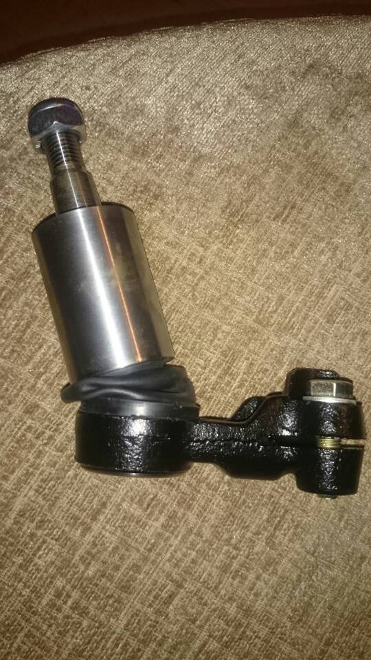
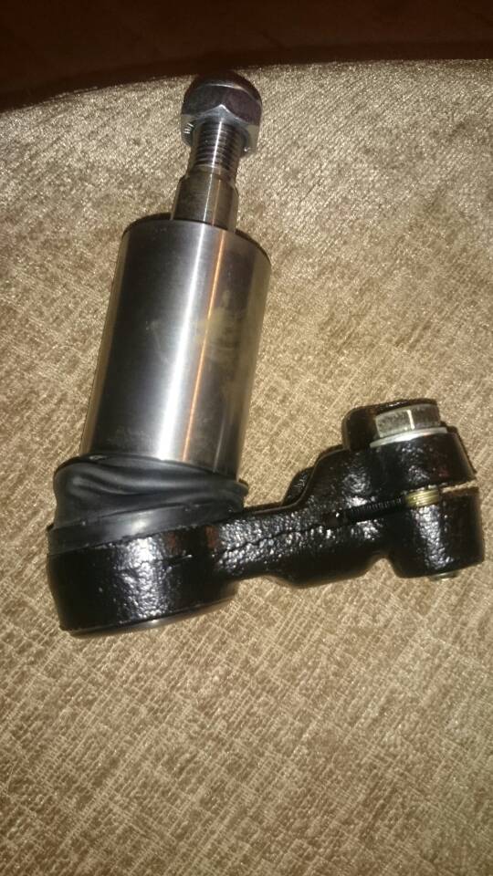
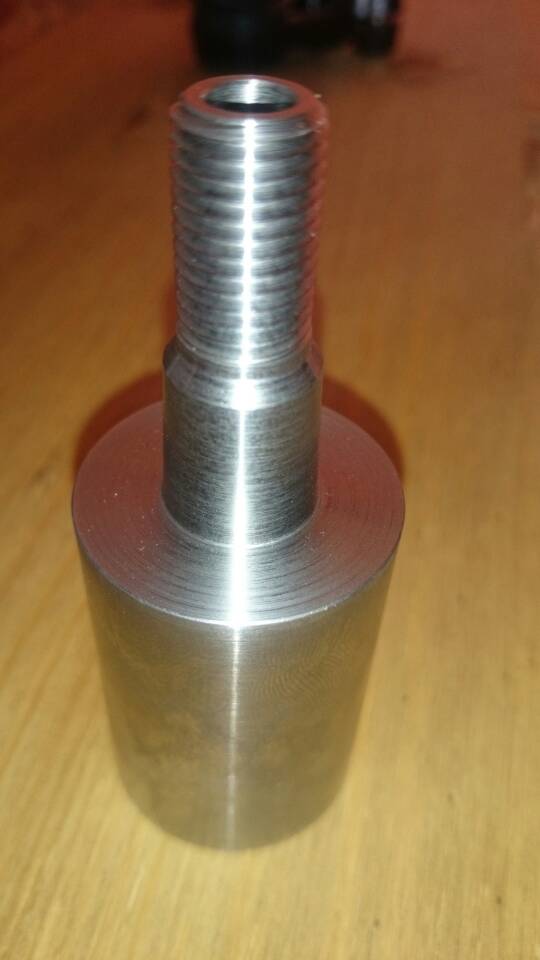
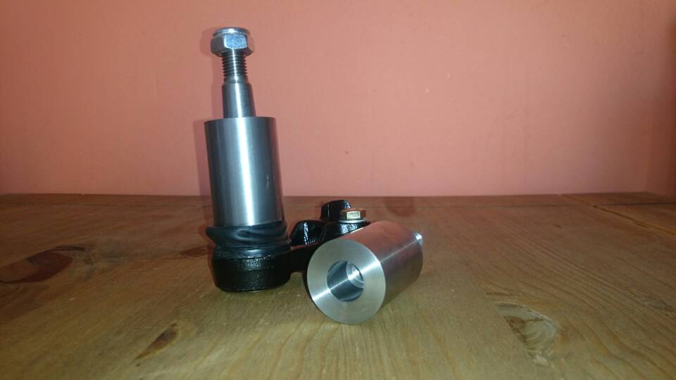
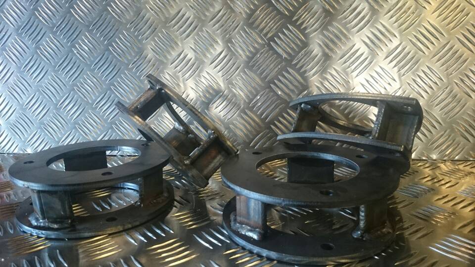
Well the machined parts I collected today, the lift plates I have made and had powder coated and there back too. I have a few sets a couple to test to destruction at work I'm making up a jig so I can apply a load of sheer force to them.

Just a case of fitting and testing when I have some camber bolts

Can't upload photos from my mobile phone tho I guess I need to be on a proper computer
 
y6ypedet.jpg
y6aha6yv.jpg
ezejuda8.jpg


Well fingers crossed this tapatalk works.... Can ya all see pics
 
Can someone please confirm that the photos are showing

Cherry on top and all that 😂
 
Sweet it works lol
Cheers for the heads up it means I can plague you lot with pics now
 
I still think that the tre extension needs to have a locking/securing method, what's the point of a nylock on the top when the internal thread isn't locking?

But they do look good!
 
Last edited:
Ok I can see your point, the part will have a flat on both sides so an adjustable spanner can be used to tighten it onto the ball joint, through the center the is a hole to allow an Allen key to pass through into the Allen key slot in the ball joint it's self so it can still be tightened as normal or undone as normal.
With the nylock on top the extension can't undo anyway but, if it's a concern you could always use thread lock on the ball joint end
Hope that makes sense
 
Yeah will lift two inches and the silver parts hopefully lift the steering arms up so I won't have to cut into the chassis legs for clearance on full droop
 
I`d be happier if the cylindrical part was twice the thickness.....but thats just me and my OCD over engineering mind..:whoosh:

Still looks good and if the material can withstand the forces involved....

Well done pal..:clap2:
 
I've 2 concerns.
1 the ball joint extension is to close to the ball itself. This will, A: pinch the boot causing grease leakage and giving a MOT failure. B: restrict ball joint movement. This will load the track rod with a bending force.
2 The internal thread needs to be locked in some way. Possibly by a bolt through the side, stopping the thread from rotating.
 
Ok I could drill through a flat face and fit a grub screw to pinch the thread and lock it in place on the ball joint would this be ok?
It's 35mm outside so is quite chunky
As regards to pinching the rubber boot the distance from the bottom of the extension to the ball joint it's self is almost the same as the steering arms the ball joint has its full range of movement with no contact.
Pics to follow with it at its own stopping point
 
pusemuru.jpg
uqehaba7.jpg


Even at this point I can still wiggle the rubber boot in the space that is available. It's not tight at all.
I could put a bigger chamfered edge around it to give a smoother surface for the rubber, if it was to deform and come into contact wit that edge the it would slide rather than slice.

Top comments by the way all. thanks for the input

:D:D:D:D:D
 
Looking at the latest pictures, the joint looks to have full movement so that's good.
Something that worries me that in the way ball joint taper isn't going to be drawn in tight enough. I'll try to explain why.
All ball joints use a taper lock type joint. This means that the taper takes all steering loads, the nut is there simply to pull the taper into place and keep it there. The taper won't turn with the nut, it is simply drawn into firm interference fit with the female taper of steering arm on the strut.
Now with your extension do dad, the nut is replaced by a threaded section inside the extension above the taper. With this arrangement, you will need to turn the taper to tighten the nut. This is going to make full tightening of the nut (threaded section) impossible due to the drag of the taper. It's difficult to explain in writing so I hope you can see what I'm trying to explain. Basically a taper is designed to prevent turning, but it must be turned for the nut to tighten fully.
Then the actual mechanics of tightening become a question too. There isn't any way to tighten the extension on to the ball joint, other than the friction of the joint itself. This will also need to be overcome.
It this moment in time, I'm not sure how to get around either of these issues.
 
Last edited:
Humm yeah I do see what you mean.... It's almost a crushed fit when tightening,
Well on first impressions just by pinching it on by hand it seems to pull up ok I'm yet to machine the flats on full a full tighten up.
Both the new ball joint and the extension faces are quite "polished" is there a lubricant that could be used when fitting that would allow the two mating faces to slide on each other and then dry. Could potentially solve that issue
 
Been reading this thread with great interest because I love an invention!! Have to agree with the above about tightening it against the friction of the taper. There's no way (in my humble opinion) that you could get the taper pulled in enough by having to turn it. Only way I can see of doing it is by splitting your component (yes I know it means more parts which might not be good). I'll try to explain in words but it may be difficult! Imagine cutting it across where the internal taper ends, put the tapered section on, and then have two flats on the remaining section to tighten it all on. Then you could possibly drill the top section and lock it with a pin. Just thinking out loud but it may take something along those lines. Assuming anyone knows what I'm actually trying to say !!!!! :confused:
 
Been reading this thread with great interest because I love an invention!! Have to agree with the above about tightening it against the friction of the taper. There's no way (in my humble opinion) that you could get the taper pulled in enough by having to turn it. Only way I can see of doing it is by splitting your component (yes I know it means more parts which might not be good). I'll try to explain in words but it may be difficult! Imagine cutting it across where the internal taper ends, put the tapered section on, and then have two flats on the remaining section to tighten it all on. Then you could possibly drill the top section and lock it with a pin. Just thinking out loud but it may take something along those lines. Assuming anyone knows what I'm actually trying to say !!!!! :confused:

I too have been thinking about this problem. The only way I can seethe taper being held correctly, is to use a 2 piece extension. This could consist of a cup shaped lower section, it's bottom would be machined to match the track rod end taper. This would allow the joint taper to be fastened correctly with the lock nut.
The upper inner edge of the cup section could be threaded with a large fine thread. The upper section would consist of the taper and thread as on the current single piece extension. On the lower part of the upper section would be a thread to screw it into the lower section. There would need to be a shoulder on the upper section to tension the thread. This would prevent bending and help keep dirt and water out.
Hopefully that makes sense.
This is I feel, the safest way forward with this idea.
 
Back
Top