stchris356

New Member
OK, I have a starting issue with my TD5 and want to do a continuity check between BCM and ECM and according to all the wiring diagrams I have it's a light green and slate wire between both(pin 34 on C0658 on ECM and pin10 C0661 on the BCU).

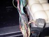
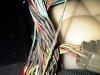
I've checked and triple checked the pins on C0658 on my ECM and pin 34 is black and green and so is 35 and 36 and there is a shed load of what appears to be glue from a hot glue gun sealing the back of the black connector, is this normal?

My rave disc has electric circuit diagrams :-
Disco series 2 2000-second edition-english
Disco series 2-2000-second edition-english export
Disco series 2 2003-english
Disco series 2 2003-english-export

My vehicle is a Dec 2001 (EU3 engine),
My question is are there any more circuit diagrams other than the above???
Thanks
Chris
 
yu are checking the wrong connector - on the Black connector (C0658), pin 34 is Green/grey (lG/S). on the Red connector (C0158), pin 34 is Green/Black (G/B).
 
yu are checking the wrong connector - on the Black connector (C0658), pin 34 is Green/grey (lG/S). on the Red connector (C0158), pin 34 is Green/Black (G/B).
Thanks for the reply, I'm aware pin 34 on the red connector is g/b but on mine the black connector(C6058) pin 34 is g/b as was expecting to find LGS:eek:
I've checked it several times as it contradicts Rave and I'm pretty sure I'm not color blind!!!!
Also did a continuity check between that pin and pin 10 C0661(BCM) and there is no connection and was hoping that would be my starting issue problem!
 
see if the G/B goes to pin2 on the Sensor-Air inlet temp at C0587.
also try the LG/S wire on the "wrong" connector - see if that goes to pin10 C0661.
 
My rave disc has electric circuit diagrams :-
Disco series 2 2000-second edition-english
Disco series 2-2000-second edition-english export
Disco series 2 2003-english
Disco series 2 2003-english-export

My vehicle is a Dec 2001 (EU3 engine),
My question is are there any more circuit diagrams other than the above???
Thanks
Chris

I dunno about more but they are different only in a few areas (lighting, A/C, Audio systems, EAT) the others are similar
 
see if the G/B goes to pin2 on the Sensor-Air inlet temp at C0587.
also try the LG/S wire on the "wrong" connector - see if that goes to pin10 C0661.

Been and quadruple checked!
the G/B wire at pin 34 C0658(black plug) has no continuity with pin 10 at C0661(BCM).
There is no LG/S wire on either of the ECM plugs but just for clarity there is continuity between pin 34 on C0158(red plug) and pin 2 of the IAT at C0567.

So I'm still trying to find the digital coded signal wire from the BCM to the ECM but there is no LG/S on the plug as Rave would suggest but BOTH pins 34 on either plug are G/B:frusty:
 
As i see in the ECM's block diagram the only connection between this one and the BCU is via the diagnostic socket:confused:.... in the workshop manual is stated "
Immobilisation
...... When the engine is cranking, the ECM looks for a coded signal from the BCU. .......If the BCU is disconnected, the engine starter motor will remain isolated by the starter motor relay and the ECM will remain immobilised. The main wiring for the system is contained within the main harness which is relatively inaccessible,


Corroborating these i'd say that the diagram is wrong cos the main harness doesnt have direct wiring between the BCU and the ECM ... there must be a connector somwhere which doesnt appear in the diagram:eek:
 
havent been able to check yet - on my toodoo list.

Mystery solved I think, been playing this morning and look at the photo's below, someone had fitted a new plug(from what, I don't know!) and cut the old one out about 6 inches down the loom which I discovered when I removed the insulation, the wire fell out of the back of pin 34 once I finially got past the they blob of glue used to seal the plug, carried out a continuity test between that wire and pin 10 of the BCU and hey presto a connection!

My next problem is getting the female pin out and replaced, the "geneius" that fitted the plug has somehow made a bit of a mess of the pin and I can't see how it comes out and was wondering if you could enlighten me please!!!
Thanks again
Chris
 

Attachments

  • IMG00030-20110812-1326.jpg
    IMG00030-20110812-1326.jpg
    172.4 KB · Views: 1,356
  • IMG00031-20110812-1327.jpg
    IMG00031-20110812-1327.jpg
    229.1 KB · Views: 682
  • IMG00032-20110812-1327.jpg
    IMG00032-20110812-1327.jpg
    227.3 KB · Views: 1,322
reet....

on the 36 way connector, there is a white (usually) plastic guard on the connecting side of the connector. Remove this and then CAREFULLY pull on the pin34 wire. there should be a rubber seal around the wire and the contact should pull straight out.
If yu were more local I would do it for you.
 
Unlike the red plug there is no plastic shield, just exposed pins and a LOT of glue on the other side if the plug, I've removed the glue from that pin (not easy) but the connector won't budge, looked at the others and there seems to be a plastic tab holding them in.
This tab appears to be missing on pin 44 (probably the reason for the glue) I'll have a dig about and see what I can do, I'd love to know where this other plug has come from????
As you have probably noticed in the pictures non(or very few) of the wire colours match!!
 
are they pins or socket contacts. They shud be socket contacts and all of the connectors I have used use an anti backout plate. can yu post a pic of the interface side of the connector?
 
No - its the anti backout plate which locks them in position, hence my concern that yours are glued in with no a-bo plate :eek:. That is why it is so named - it is supposed to stop the contacts from "backing out" of the housing.
 

Similar threads