Wiring Light bar, help required.

This site contains affiliate links for which LandyZone may be compensated if you make a purchase.

brettguise

New Member
Posts
282
Location
Stourbridge, West Midlands
Hi guys, I purchased a light bar second hand and want some spots to go on it, I don't need to blind people but just a bit more light would be nice. I don't know if anyone has any recommendations, I don't want anything expensive just something I can smash off trees etc.

Something like this kind of?

UNIVERSAL CAR 4X4 OFFROAD FOG SPOT LIGHTS SET OF 2 | eBay

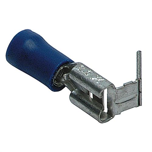
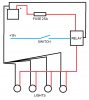
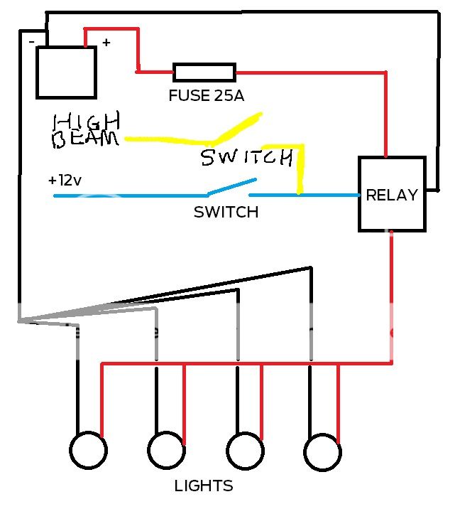
Also I need to know the simplest way of wiring this up, im no electrician. From what I gather correct me If I am wrong but.

Ground each light to the actual light bar on the bolt that bolts the bar to the light. Connect the lives together and then run one live wire down into the engine bay, what about a neutral? I thought a circuit required a neutral wire as well?

I run that wire into a fused relay being the simplest relay available?
I then run a wire off to the battery positive and a wire off to the main beam wire with a switch along that wire so I can switch the spot lights off if I want to. I don't mind about the switch being inside the car, I could maybe do that at a later date just something as simple as possible.

Whats the best way to connect the live to the car battery, I've never introduced a new wire.

Correct me If I am wrong, I have looked at a lot of pictures and I just want to make sure I have this right.

Would this be a good wiring kit?

Fog Spot Work Light Spots 12v Wiring Kit 30 amp Relay Switch | eBay
 
You'll want to piggyback from the main beam circuit to close a relay when main beam is activated.
Then, the power feed of the relay needs to be run to your lights.
There is no "neutral" in auto electrics.

Make sure the cable you use to feed the relay is of sufficient guage so as not to melt the plastic sheath when the power goes on (add up the wattage of each light).
You can make a connection to the battery with a ring terminal - undo the battery clamp, slide out the pin insert ring, slide the pin back in and nip up the connector again.

You may well need to run an earth wire back down to the engine bay depending on how the light bar fixes to the roof - if there's paint between the lightbar and the roof it's not going to earth properly.
 
Before wiring up anything you need to consider what size cables you need. Think back to ye olde skool days - ohms law :)

amps = watts/volts

You've mentioned fitting 2 lamps, so lets assume they're both 55W each.

amps = 110/12
amps = 9.1 so call it 10A

If you fit 4x 55W (or 2x 100W) then assume roughly 20A.

So your cable will need to be 2mm (for 10A) or 4mm (for 20A). This takes into account the voltage drop over a 3 metre long cable run (see here About Cable Sizes ). You'll need the same for the ground cable - while you can ground it through the light bar you'll get a better ground connection in the engine bay, and thus brighter lamps. Its an arguable arrangement, some use the light bar some don't. Up to you.

Note there is no neutral in DC circuits, thats AC only ;)

Using a fused relay is a good way to go. Don't forget to select the appropriate size relay (as well as the fuse). I usually use a 30A relay for lighting circuits. Take the feed directly off the battery (via another fuse).
 
I wouldnt do it off the main beam, just run it off a seperate switch as you will only use them when laning. This gives you the advantage of turning your headlights off if going through a deep ford and just having the roof lights on. Reason for this is

A) headlights dont work underwater and it will all go dark very quick
B) Hot headlight glass + cold water = cracked headlight


So you want to fit a switch in the cabin, 12v feed spliced off one of the other feeds for the stereo or ciggy lighter to one side and then from the switch to a relay that you can put under the dash (the bit under the steering column is ideal) 12v feed from the battery through the bulkhead to the relay and then an earth either going back to the battery or to the body somewhere.

Then a wire out to the lights. i did mine up the drivers A pillar inside and then drilled a hole in the roof behind where each light would be. I then spliced them altogether and connected them to the feed wire behind the overhead console. Its a lot of work as you have to take bits of trim off etc but looks neater afterwards. Dont forget to use gromets where wire passes through the body.

Also if you get LED worklights they are lower wattage so you dont have to go as heavy on the wire and make sure the fuse used is a lower rating than the lowest spec wire you use :)
 
Last edited:
Ok slightly confused now but I will run through it again as how I understand it.

Piggy back each live wire to one main live that I run down the side of the windscreen into the engine bay. Can I use these? Do I have to tape them up or something?

Q240.jpg


Piggy back each earth wire and run one single earth down into the engine bay and earth off the body. That way it will give a stronger light beam and ensures I have a correct earth.

Ill use a 30amp rated cable and fuse as I plan on 4 or 6 55w lights.

So I need a fused relay and a fuse in the line off the live feed from the battery to the relay?

I will also consider the option of not coming off the light but coming off a 12v feed inside the cab.

If I do come off the light where is the best place to come off and again do I use a piggy back connector on that line as well, just cut the main beam wire, piggy back connector and feed off to the relay?
 
This is how i would do it

attachment.php


Get an inline blade fuse holder, a standard 30A 4 pin relay and a switch of your liking. Make sure all earth cable is the same size or bigger than the largest power cable you use. You can use piggybacks or just twist 2 wires together and use and bullet crimp. Best way is solder them but can be awkward in some places.

Avoid scotchlocks as they are unreliable and can lead to a whole host of electrical issues.
 

Attachments

  • Spots.png
    Spots.png
    18.9 KB · Views: 2,843
Subbed as ill be doing my wiring soon ! The above diagra is perfect ill be doing 2 setstho
so 2 relays 2 switchs ect , 2x outside spots , 2xinside spots
just because on laning i cant see round corners so the 2 outside ones are facing outwards slightly to help with corners
 
This is how i would do it

attachment.php


Get an inline blade fuse holder, a standard 30A 4 pin relay and a switch of your liking. Make sure all earth cable is the same size or bigger than the largest power cable you use. You can use piggybacks or just twist 2 wires together and use and bullet crimp. Best way is solder them but can be awkward in some places.

Avoid scotchlocks as they are unreliable and can lead to a whole host of electrical issues.

Thats a really nice idea but I ideally wanted it to come on with my main beam but also to be able to come on by a switch and also off with a switch so a three way switch in the cab and also tapping into the main beam. Hmm.
 
Thats a really nice idea but I ideally wanted it to come on with my main beam but also to be able to come on by a switch and also off with a switch so a three way switch in the cab and also tapping into the main beam. Hmm.

but you said you were a leccy pudding who doesn't even know how to use a piggy back crimp.

do you have a multimeter or a proper crimp tool? pliered crimps are not great.

i'd either find someone to 'help' or simplify it so you have a chance of not mucking it all up. You can always fit more switches later :)

I did say Ideally, but I did say in the original post I want to come off the main beam and have a simple switch under the bonnet to disable the beam if need be. I'm thinking of just buying a wiring kit and having a go.
 
I would go with the method outlined by Tuskenraider, rather than wiring them to the main beam headlight circuit; they're are roof mounted lights and as such are unlawful for road use. By separating the circuits any failure of the main headlight circuit while you're out on a laning trip shouldn't have any effect on the roof lights so you should be able to see your way to somewhere safe where you can make repairs.

The only addition/alteration I would suggest would be building the system as two pairs of lights instead of a single system of four lights with a switch for the outer pair and another switch for the inner pair. Maybe a rotary type switch would work here; four positions, Off, Outers lights only on, Inner lights only on, All on.
 
I did say Ideally, but I did say in the original post I want to come off the main beam and have a simple switch under the bonnet to disable the beam if need be. I'm thinking of just buying a wiring kit and having a go.

go for it, you can always ask questions here if you get stuck :)
 
Ive ordered 6 spot lights and a wiring kit, I will give it a go, I think the kit is a simple on off switch kit so I will go down the route of wiring that like Tusken has said. I will update Wednesday If I get stuck. If it works ill take some pictures for people to see as I cant find a single topic with pictures of a setup rather than wiring diagrams :(
 
Ive ordered 6 spot lights and a wiring kit, I will give it a go, I think the kit is a simple on off switch kit so I will go down the route of wiring that like Tusken has said. I will update Wednesday If I get stuck. If it works ill take some pictures for people to see as I cant find a single topic with pictures of a setup rather than wiring diagrams :(

probably because it's that simple :D :p
 
Just did mine a few weeks back - One wire with all 4 lights piggy backing off it, down under the rubber of the windscreen, under the bonnet, into a connector block, fused via the lighting fuse under the bonnet, switched by a switch mounted in the side of the instrument binnicle.

All wires neatly tucked away, and those running along the bar through an old length of shower hose just for a bit of protection.

you didn't use a relay?
 
Thats a really nice idea but I ideally wanted it to come on with my main beam but also to be able to come on by a switch and also off with a switch so a three way switch in the cab and also tapping into the main beam. Hmm.

Quite simple really, here you go:
9b209bf716d5b74bdeb44bec14dacf8f.jpg
 
Trax - I don't believe I did - it all works, mind.

Why would I need a relay for a simple setup like that - bearing in mind I was thinking back to my GCSE days and a few lessons we had on simple circuits.
 
Back
Top