samc88
Drivels spiritual representative
- Posts
- 2,838
- Location
- Anglesey, North Wales
I know I have another rebuild thread but thats more a collection of random photos
As most know, there is also a 90 on the go in our garage which is my brothers and the time has come for an engine rebuild. (Yes that project is still on the go just havent updated it for ages)
Stage 1: Getting the engine ready to lift onto the engine stand
Before doing anything, mark up the clutch and the flywheel so you know which way it goes when re-fitting. It makes life much easier if there is a chance of different hole centres in the clutch - just something I learnt through my own experience in work. The first thing to take off will be the clutch assembly
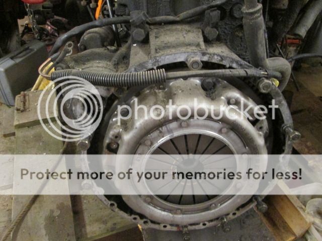
As the engine spins when you try and crack open a bolt, the proper timing pin was placed into the flywheel to hold it in position to stop the engine turning. (you could also either have a socket on the crank pulley or jam the ring gear if starter is removed)

The 6 retaining bolts were then removed using a 13mm socket
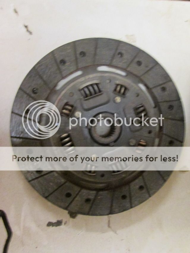
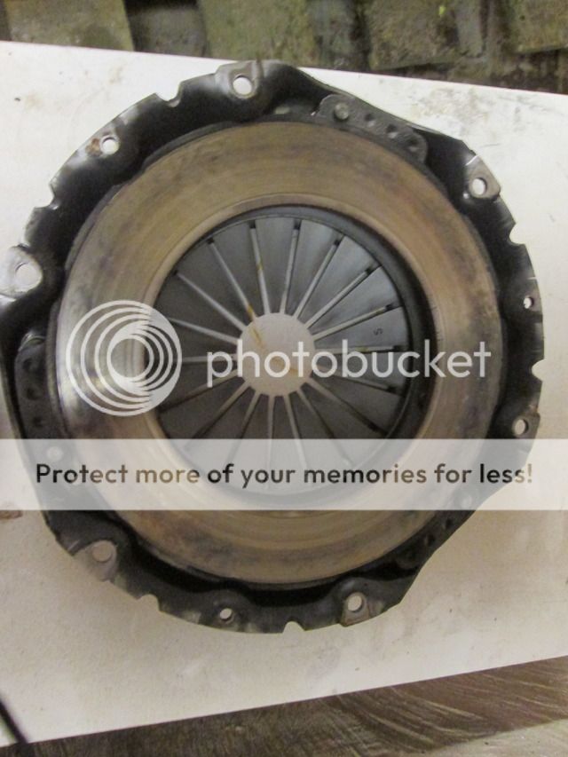
Once the assembly was removed, the bolts were put back in place so we dont lose them.

The flywheel bolts were removed using a 22mm socket on air driven impact gun, note the big retaining plate/ washer behind the bolts along with the dowel meaning the flywheel can only go back on one way

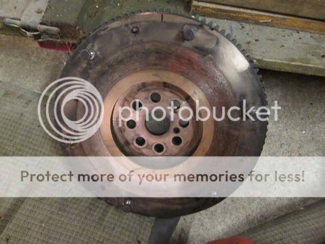
Revealing a rather oily flywheel housing, comfirming my suspicion that the rear crank seal is passing oil

Before taking the housing off, the starter motor was removed using 17mm socket and spanner. The earth bolt for the cable from the block to the motor is removed with a 13mm socket.

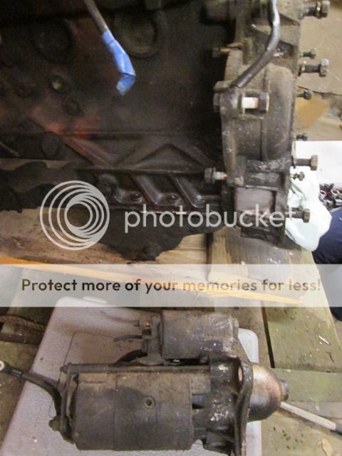
Next the flywheel housing itself is taken off, again with 17mm socket. There are 6 bolts inside the housing and 2 above. These 2 bolts have a bracket on them to hold wiring. These are also longer than the other 6

Its all pretty oily
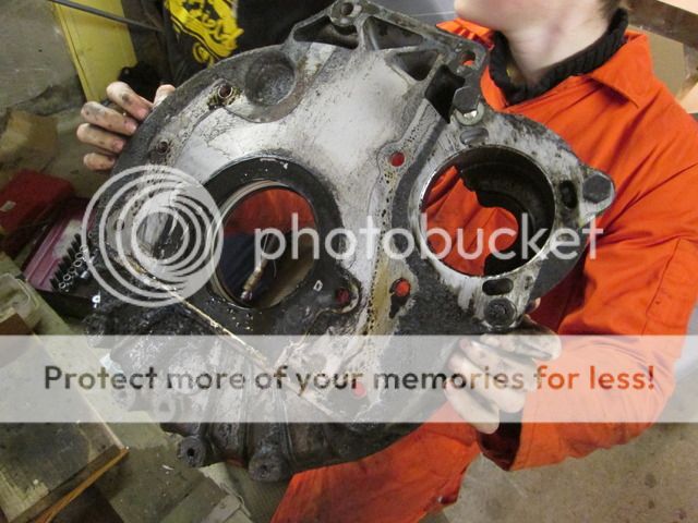
Ready for lifting tomorrow evening

Tools needed:
Clutch assembly - 13mm socket
Flywheel - 22mm socket
Starter motor to engine block earth bolt - 13mm socket
Starter motor - 17mm socket and spanner
Flywheel housing - 17mm socket


") I did notice the extra bungs. Are pistons and big ends still the same?
I did notice the extra bungs. Are pistons and big ends still the same?