SLS raise/lower remote - faking it?

This site contains affiliate links for which LandyZone may be compensated if you make a purchase.

David Pye

Active Member
Posts
623
Location
Newcastle Upon Tyne
Hi guys,

I am trying to see if it is possible to wire in a SLS raise/lower switch for my Disco 2. I don't want the expense/hassle of a wireless remote, so am looking to see if I can wire something in. I know I could do something dirty direct to compressor/valves, but the nicer way would be to emulate the signal from the remote.

I note on the disco electrical manual that the SLABS ECU:

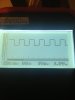
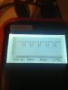
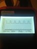
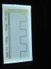
An input is received from BCU pin C0660-12 to SLABS ECU C0655-12 on a WU wire. This input is the SLS raise/lower command from the remote handset.

Anyone know what form this signal command takes? If I know, I could make one of my PICs generate it :)

Cheers,

David
 
that's a good idea...the problem is tnhat RAVE is quite vague on this area and i couldnt figure out what kind of signal is there, according to general description of BCU the signals are:
-Logic 1 when V ≥6V
-Logic 0 when V ≤2V,
then they say in operation:
RAVE said:
SLABS raise/lower
Before enabling a SLS vehicle raise/ lower request, the BCU checks the logical condition of the following inputs:
l Ignition state.
l SLABS raise request.
l SLABS lower request.
If the ignition switch is in position 0 or I, the vehicle raise/ lower request is off.
With the ignition switch in position II, and the 'SLABS raise' request and 'SLABS lower' request both off, the vehicle
raise/ lower request output is driven at 25 Hz with a 50% duty cycle and the vehicle height remains unchanged.
If the 'SLABS lower' request input is on, the vehicle raise/lower request output is driven at 25 Hz with a 25% duty cycle,
lowering the vehicle.
If the 'SLABS raise' request input is on, the vehicle raise/lower request output is driven at a 25 Hz with a 75% duty
cycle..

IMO your idea is doable but the best and 100% certain thing is to find somebody with a remote, ask him to raise/lower the vehicle while you check the output from BCU/input in SLABS ECU on that wire with an osciloscope...then you'll be able to replicate the signal somehow if you are smart enough...and it seems that you are;)
 
Last edited:
Hi Sierrafery - that is just the information I need.

I can easily generate a 25Hz square wave, and use pulse width modulation.

What I think I will do is put a switch on the rear body panel by where I put my trailer socket so I can press up/down when hitching up.

I'll update with what I come up with. It should be able to be done for maybe 10-15 quids worth of parts :)

please do that
 
The three piccys attached show the PIC generating a 25Hz sine wave with 50%, 25% and 75% duty cycles. With a bit of luck, this should make the SLABS ecu send the air suspension up and down. I will have a look and see if the SLABS pin has a 50% cycle 25hz wave on it to begin with, and if so, I will try substituting it for my signal. I will need a small amount of interface circuitry to boost the volts, as my poor little PIC uses 5V, not 12V.

But it's a start!
 

Attachments

  • IMG_0591.jpg
    IMG_0591.jpg
    135 KB · Views: 477
  • IMG_0592.jpg
    IMG_0592.jpg
    136.6 KB · Views: 410
  • IMG_0593.jpg
    IMG_0593.jpg
    157 KB · Views: 430
Brilliant:).... IMO make a test with 5V before you boost the voltage cos the circuit within the SLABS ECU might recognise the signal regardless of the voltage if it's configured especially to "decrypt the waves"
 
The three piccys attached show the PIC generating a 25Hz sine wave with 50%, 25% and 75% duty cycles. With a bit of luck, this should make the SLABS ecu send the air suspension up and down. I will have a look and see if the SLABS pin has a 50% cycle 25hz wave on it to begin with, and if so, I will try substituting it for my signal. I will need a small amount of interface circuitry to boost the volts, as my poor little PIC uses 5V, not 12V.

But it's a start!

sierrafery

Brilliant.... IMO make a test with 5V before you boost the voltage cos the circuit within the SLABS ECU might recognise the signal regardless of the voltage if it's configured especially to "decrypt the waves"
__________________
been watching this Thread! some really tech **** going on!! haven't a clue what the f--- it means but looks good!!!
keep it up!!:dance:
 
FWIW, here's the code for the arduino to generate the SLS signals.

//Sketch for land rover discovery 2 SLS controller. (prototype!)
//Author: David Pye [email protected]
//Version: 0.1 13/12/12
//Licence: GNU GPL v3.0

#define SLABS_PIN 13 //pin to connect to the SLABS ecu.
#define PIN_UP 10 // grounding this will send us up
#define PIN_DOWN 11 //grounding this will send us down

#define FREQ_HZ 25

int cycletime = (1/(float)FREQ_HZ) * 1000;


int dutycycle, ontime, offtime;

// the setup routine runs once when you press reset:
void setup() {
// initialize the digital pin as an output.
pinMode(SLABS_PIN, OUTPUT);

pinMode(PIN_UP, INPUT);
pinMode(PIN_DOWN, INPUT);
digitalWrite(PIN_UP, HIGH);
digitalWrite(PIN_DOWN, HIGH);
}

// the loop routine runs over and over again forever:
void loop() {

if (digitalRead(PIN_UP) == LOW) dutycycle = 75;
else if (digitalRead(PIN_DOWN) == LOW) dutycycle = 25;
else dutycycle = 50;

ontime = cycletime * (float)dutycycle/100;
offtime = cycletime - ontime;

digitalWrite(SLABS_PIN, HIGH);
delay(ontime);
digitalWrite(SLABS_PIN, LOW);
delay(offtime);
}
 
Probably going to be next weekend before I do, because I am away from home this week and I had some grief last week getting the air susp off the bump stops in the cold after everything had been jacked up (comp duty cycle exceeded...!)
Last thing I need is to break the car here so I can't drive it home to where my tools are ;-)

I will try at home to be safe!
 
Brilliant idea. In my past life I also coded C for PICs, handy uCs ;-) Does anyone know if the remote is RF or IR, also is it linked to the ECU somehow? If it's a single code and IR two alternative options exist:

1. The PIC could simply fire an IR LED and replicate the code
2. Use a cheapy remote control to 'learn' the IR and use that...

Uhm, bet the remote is RF, makes it all more difficult!

Lea
 
PI had some grief last week getting the air susp off the bump stops in the cold after everything had been jacked up (comp duty cycle exceeded...!)
Last thing I need is to break the car here so I can't drive it home to where my tools are ;-)

if you have this kind of problems unplug all electric connectors in the compressor housing and improvise a wiring as to feed the compressor and the two air supply valves at the same time directly from the battery... take care to cut the feed when you see that the aproximative height is reached...then let everything unplugged and if you dont have a leak along the system it will stay on level for days....but usually the compressor exceeds the duty cycle if the system looses air somewhere and it must compensate it.
 
Right, the short answer is this:

Looking at the pin in question on the SLABS ECU, here's what you see in 'idle' condition, ignition at position 2:

(It's a 50% duty cycle, 25Hz 12volt square wave as expected).

The arduino (as expected) cannot manage to trigger any exciting behaviour itself - it *will* need a small transistor to enable it to do it's thing. But this isn't going to be a problem, but will take me a few more days :)
 

Attachments

  • IMG_0602.jpg
    IMG_0602.jpg
    122.8 KB · Views: 432
Well, now it works :)

I have a switch which makes the SLS go up if you press it one way, and down if you press it the other.

I just need to try to get some smaller PIC boards then I will have something I can fit and forget :)

Is anyone else likely to be interested in a kit form of one of these? :)

Cheers,

David
 
Back
Top