Sam's 2.5 N/A diesel strip down and rebuild thread

This site contains affiliate links for which LandyZone may be compensated if you make a purchase.

samc88

Drivels spiritual representative
Posts
2,838
Location
Anglesey, North Wales
Righty ho, I know this is covered in my series rebuild thread but thought it may be helpful to others (especially those with early 90/110's and stuff) if I posted the relevant bits of the engine rebuild in this section. (if thats alright?)

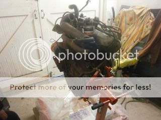
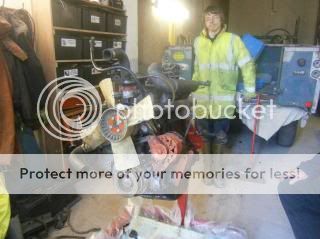
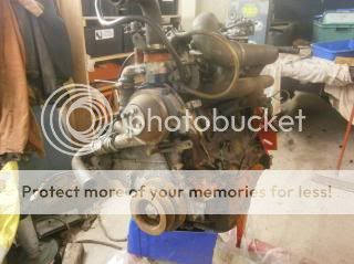
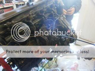
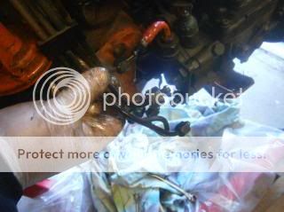
Few pics of hoisting the engine out of the landy

P2030810.jpg


P2030811.jpg


P2030812.jpg


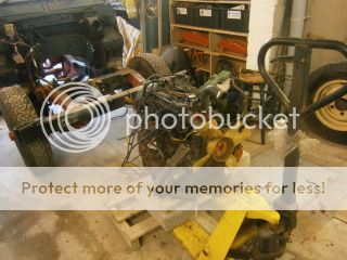
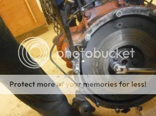
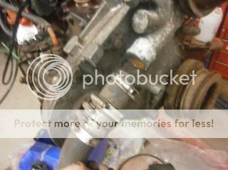
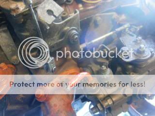
First job when working on the engine was to remove the clutch by undoing the bolts that are located around it. These came off fairly easily


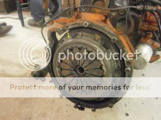
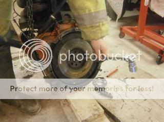
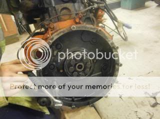
With that out of the way, the next task was removal of the flywheel which is a very heavy peace of kit. This was removed by the bolts in the centre. The yellow marker was on the clucth so that we knew which way to put it back on when it came to refitting. We also did the same to the flywheel but this time with a centre punch


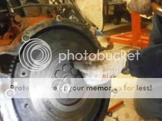
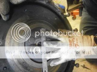
To undo the bolts, you need to stop the flywheel from turning. We did this by using a pry bar against the teeth of the flywheel ring gear. The bolts are tight so we used a breaker bar. If anyone's wondering, this has to be done if the engine is going to be fitted to an engine stand.


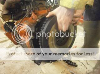
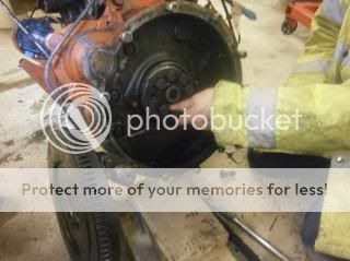
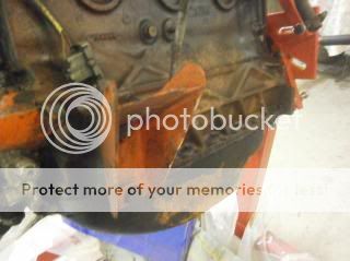
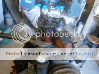
After removing the flywheel, to be able to place the engine on a stand the flywheel cover needs to come off


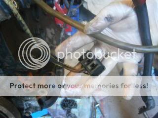
Before removing, there was a bracket holding some wiring and piping near the fuel lift pump which was removed just to give a bit more access.


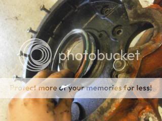
On this engine, the rear crankshaft oil seal was leaking so will be replaced. While we were at this stage it was decided to remove it.


With all that out of the way, we then bolted the engine to the engine stand


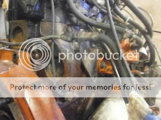
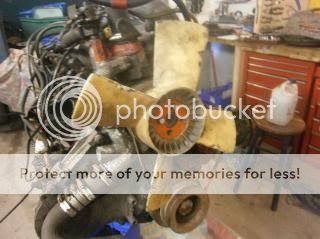
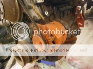
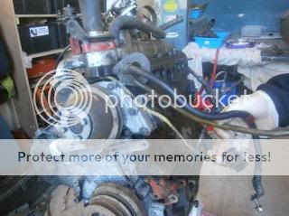
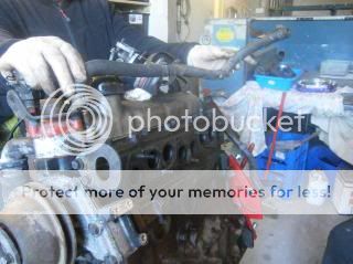
After the engine was bolted to the stand the first thing we did was to remove the fan, fanbelt and the alternator. The fan (a type of plastic on this) is bolted the water pump pully with 4 bolts which were pretty simple to undo once the fan was stopped from rotating.


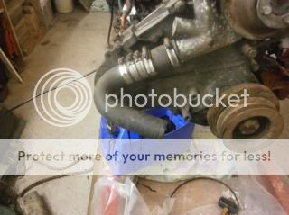
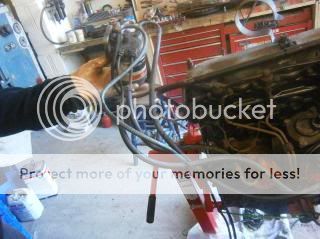
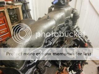
This pipe was the next thing to be removed. To do this, all thatwas needed was to loosen the jubilee clip closest to the engine block


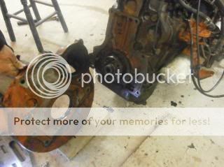
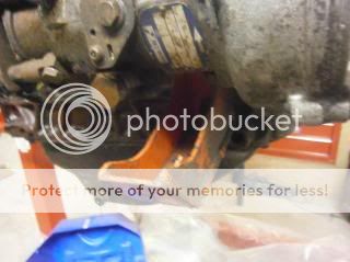
The engine mount brackets were then the next thing to be taken off (well the passenger side one at least, I left the other one for a while to do something else)


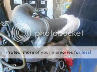
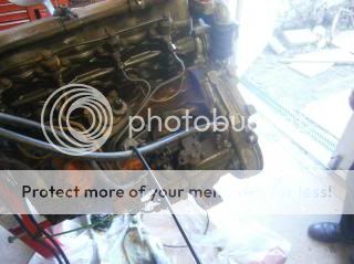
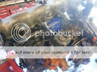
Next to be taken off was the inlet and exhaust manifold. These are 2 separate parts so if you undo all the bolts make sure one does not fall.


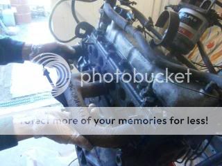
Some of the pipes were then removed as well as the plug for the alternator


Much better access to work now :)


The fuel filter was the next thing to go.


These hoses had to be removed before it could be taken off. When the hoses are taken off the pump, it is important to cover where the hoses fit on to the pump to stop dirt getting in as everything has to be clean.


The injector pipes were next. These were removed through the use of injection pipe spanner (like 3/4 of a ring spanner with an open end to slot over the pipe )


The heater control thing above the thermostat was next to go, this was undone with an adjustable spanner,


The next thing we did was to remove the injectors. To remove the injectors, the 2 bolts holding them to the block were removed and a brass drift was used to "lift" the injector up to be removed (it makes more sense in real life :) ). Before removal, the injectors were each numbered so we knew which injector belonged to each cylinder. The spill pipe running along the top of the injectors also has to be removed. Its worth noting that at the bottom of the injectors there is a copper washer, some came out with the injector but another was left in the hole.


The next thing was the cylinder head, the first task being removal of the rocker cover, held on by 3 bolts.


A bit of thick string/ rope was passed around the rocker assembly to keep it all together. This didn't need to be taken apart so will stay like this and just be cleaned with paraffin.


The glow plugs were removed at this point to avoid damage


The pushrods were removed. It is important to keep them in the right order so a bit of cardboard numbered 1 to 8 and each pushrod pushed through by the corresponding number (1 being the front of the engine )


The cylinder head bolts were then cracked off by going round in opposites (it does say in the book which order to this in). They were first done with a breaker bar and then a ratchet and socket could be used.


The thermostat was then removed. When it was replaced previously my granddad smeared copper grease around the studs which meant the bolts came out easily. I've heard of people having trouble with sheared bolts but I think doing this when it is replaced helps to stop bolts siezing.


The next thing was removing the valves. For this a valve spring compressor was used.


With the springs compressed, the collets could be removed. It is important to keep each component with the valve it came from and to keep the valves in order.


We found that the hotpoints (te part where the fuel comes through were cracked. To remove them we used a punch down the injector hole to push them out of the head surface.


Since the head was now disassembled, the head gasket was carefully scraped off and then the head was left in a large bucket of parrafin to help clean/ degrease it.

Whilst it was soaking it was decided to remove the old worn starter ring gear. The flywheel was held in the vice and a hacksaw used to cut through the gear making sure not to cut into the flywheel metal itself.


This was then placed on the floor and held upright. A sharp cold chisel was used on the cut made by the hacksaw and hit with a lump hammer. When doing this it is important to wear safety glasses so bits can't fly into your eyes as well as wrapping a cloth around where the cold chisel will strike, keeping the airborne parts low.

Next up the sump, all of the oil was drained out of this previously.


Its not too bad inside, just a small amount of thick oil in the bottom.


Inbetween jobs, I also decided to spray up the manifold with some High temperature silver.


The headgasket was again scraped off as well


Now for the removal of the pistons. The two big end bolts were removed.


The bearing shells are very worn, in need of replacement


The piston was then pushed up the bore using the rubber handle of a hammer so as to avoid causing any damage.


The crank looks good


All four pistons removed


Interesting to note, the engine has been rebored at some point in time with oversize pistons being fitted.

Then it was back to the engine as we wanted to take the timing belt cover off, we originally thought it would have a chain but discovered it was actually a belt (would have found that out by looking in the book but ah well :rolleyes: )


The water pump was taken off first, unfortunately the two lower most bolts sheared, one sheared and one had its threads stripped.


We tried a stud extractor but that made it shear even closer to the casting


Next the bolts around the timing cover were removed, these were placed on a matt in the order they were taken off as they are different lengths so it would save faffing about later trying to find the right size bolts


After the cover was taken off, the bolts were put back in the right place so we didn't lose them and then inside the timing cover and the cover plate itself was cleaned with some horrible smelling "cleaner", still debating whether its actually degreaser or someone's just had a pee in the bottle, whatever it was it seemed to work :D
 
The head was washed off with paraffin to get all of the grinding paste and dirt out of it and the first job was to do the hot plugs. We weren't able to get the roller pins out as they were solid so they were reused.

Grease was smeared around the plug to help hold it securely in the head.


It was then placed on the head, locating the recess in line with the roller pin


It was then tapped in with a rubber mallet until almost flush and then gently tapped with a hammer and a brass drift until pretty flush with the rest of the head (ideally proud by a thou or 2 according to JamesMartin) We don't have a dti so this was done by feel (you can feel with your fingers if its flush or not but a DTI would be more accurate) and it should be within the tolerance specified in the book


The valve components were then washed in paraffin (one at a time so as not to get things mixed up, this is important with valves) and then the valves were replaced, starting with No. 1 at the front (the thermostat end of the head)


The valve was pushed through and then the oil seal was put in place. In the head gasket set there is a pack of 8 oil seals and they are of two different types, one type has a spring in the groove and a smooth exterior, these are for the inlet valves only. The other type is just a plain groove with 4 little rib type things along the outside and these are for the exhaust valves. These will push down the valve and will sit in a groove so they can't come out again.


I don't have any pictures of this next bit so will have to try and explain, the spring and the collet retainer plate (this will only fit on one end of the spring so it will fit properly) were then slid over the valve stem. A valve spring compressor was then used, keeping it central to the valve, the spring was compressed enough to be able to put the collets on correctly. When the collets are both on, release the spring compressor but very slowly so you don't get your fingers stuck. The collets should now be in place preventing the spring and the plate from coming up the valve. Next you can gently tap the plate holding the collets to help bed them in.

I hope that makes sense to you?

Anyway here's the head with the valves done


Glowplugs and the injectors were next to go back on, the glowplugs were given a clean and then put in the head and torqued up to 18 lb/ft (the book says between 11 and 22 lb/ft is correct.

The injectors were then cleaned with a paintbrush and parrafin, (away from the nozzle and the hole fuel enters to stop any damage occuring) to get rid of the carbon and old oil that was baked on a couple of them.

Before fitting an injector, a copper washer must be fitted to the bottom of the injector housing tube. The old one may still be in there so be sure to take it out. If its tight, you need to get a screwdriver and tap the washer with a hammer, this will eventually buckle it enough to allow it to be removed. Only 1 was stuck like this on our head and this is how we removed it. The rest came out with the injectors. (there is also a steel washer underneath the copper one)


To help allow the washer to be located centrally you can put it on a screwdriver and put the screwdriver down the injector hole and slide the washer down it.


The injector can then be put on, ensuring it seats correctly (if it doesn't it either means it isn't sitting correctly on the copper washer or it is just tight on the threads, in which you can lightly tap it down.


The head complete except the rocker shaft


And the rocker shaft placed temporarily on the head

 
Next job was to check the bore size. We used some internal callipers and then measured the distance with a digital vernier. Doing this we found the bores to be standard size with next to no wear in them at all.


The piston rings were then checked to see what the gap was like. To do this a piston ring was put in the bore and using feeler gauges we found the gaps to be about 1.5mm far bigger than any of the specs given in all of the books we have (about 3 times bigger than it should) so new rings will be bought on monday from L & R in Bryngwran.

The next item on the agenda was the 2 broken studs at the bottom of where the water pump goes. To get at these, it was decided to take the whole front of the engine off. We did try drilling a stud out but the drill wouldn't touch it and there was too much stud to drill out anyway.


The 2 nuts on the idler wheel bracket were slackened allowing the tensioner to move. The belt can now be removed.


The camshaft pulley was then taken off.


Its worth noting that each of the shafts has a woodruff key holding the pulley in place, in the case of the crankshaft, it has 2.


The injector pump pulley wouldn't come off using a pry-bar so we had to make a puller. I found a disk of steel in the workshop / shed that was big enough. The distance between the holes was measured and then marked on the disk. The holes were then centrepunched, drilled through with a pilot drill and then drilled to the final clearance hole size for the bolts


It worked quite well :)


The crankshaft was next removed using a pair of pullers (the ones with a pair of legs and a thread running down the middle. This picture shows where the 2 keys sit


The oil seal was leaking here and will be replaced.

Next was to get the injector pump off, this little connector on top of the pump was removed, the outer sleeve is tapped forward until you can lift it off the pump. Before taking the pump off we scribed a line on it and the casting on the front of the engine so we can put it back in line properly as it came off.


The bolts and nuts were then removed using a 13mm spanner


With the pump off we could now start to remove the casting at the front of the engine, this required use of prybars, a large mallet, a fox wedge and a wallpaper scraper to try and get it to move.

Eventually:


The 2 sheared bolts


The longest one was tackled first, this was heated up using the gas torch


An 8mm stud extractor socket was used with a tommy bar to unscrew the bolt out of the casting


We couldn't use the stud extractor on the other one as there wasn't enough protruding out of the casting. The plan we came up with was to weld a nut on to the end of the thread and then use a spanner or socket to undo it.

The Arc welder was chosen for this because it was quicker to set up


Success :)

 
The next thing we did was to rotate the engine so the sump was on top. We had found the crankshaft to have a good deal of end float so whilst we're at it the main bearings might as well be checked, good job we did :)


The oil pump was taken off to give more room. There are 2 bolts with a tab washer on each holding this to the block. The tab washers are knocked out the way with a punch and the bolts undone. The mallet was used gently to persuade the pump to come off :)


With that out the way, it was time to undo the main bearing bolts. These were first cracked off using a socket on a large breaker with a pipe on the end for added leverage


With the bearing cap taken off, the crankshaft could be lifted out


The rearmost bearing is much thicker (widthways) than the other 4


Before putting the pistons back in the bores, it was decided to run a glaze buster in the bores. Before doing this the oil pipes in the block which point upwards (into the bore) were removed.


Here is where they sit. They will only go one way due to a locating peg


The glaze buster in the drill


The oil pipes could then be refitted and the bolts torqued up.


As there was endfloat, new thrust washers were bought. Here they are sat on the third bearing housing (looking from the front) A smear of grease on the side helps hold it in place. you can tell where they go because there is like a shelf either side of where the bearing goes for the washer pieces to sit on.


The new main bearing shells from C & A in Bangor :) (you can see the wider rearmost bearing shells)


Before lifting the crank back in, oil was squirted on the bearing faces. This is so that when the engine has its first start there is oil in the engine so it doesn't run dry.


The crank was cleaned and put back then the first 4 bearings were put back on.


The rearmost bearing shell housing has an oil seal either side which needed replacing (the L shaped bit on the side)


A bit of hylomar helps give a good seal and hold it in place


The bolts were then torqued up and then the oil pump was put back on (replacing the gasket as well when it was fitted)


Three pistons, minus the rings.


Each piston was then carefully cleaned using an old piston ring to clean out the ring grooves. The piston was placed carefully in the vise for putting the rings on. We found the bores to be oversize so piston rings that are 20 thou oversize are fitted


I haven't got any pictures of actually putting the rings on but will attempt to describe what we did. The rings were coated with oil to help lubricate them. The gap was opened up using a pair of piston ring pliers (like these http://www.machinemart.co.uk/images/library/product/large/04/040210428.jpg )

As the gap was opened, the ring was then slid down over the piston until it reached the right groove. The oil control ring was done first, this has a spring in it which makes it a bit fiddlier than the others to put on.

With the piston rings fitted, it was time to put them in the engine. Before doing this though a big end bearing shell was fitted to the end of the connecting rod and oiled up. The piston was oiled and put in the bore a short way and a piston slip (like this http://www.westcountryhardware.co.u...ab33525d08d6e5fb8d27136e95/C/L/CL-1801257.jpg ) fitted over the piston until it covers the bottom ring. It is then tightened up to compress the ring, it has to be tight otherwise the piston won't go in.

Once the rings are compressed the piston can be knocked in, A lump hammer was used, knocking the top of the piston with the wooden handle, holding the metal hammer head in the hand. As the handle is wood, it won't damage anything as it is softer than the metal. The piston is knocked down until the bearing shell touches the crankshaft (which is oiled as well) then the other half of the bearing can be fitted. Its worth noting that the bearings will only fit one way. On each bearing shell, there is a little tab on one end and when the bearing shells meet, the sides with the tabs touch each other, e.g. the plain sides of the bearing are on the same side of the engine. (Hope that makes sense)


As we want to fit a brake servo, there a little thing above the oil pump which has blades in it which rotate and make up the air pressure for the servo (its hard to explain). Anyway, the plastic blades were removed before so we need to refit them.


They fit in the rectangular slots on this eccentric. they shouldn't be tight so when the engine runs and the eccentric rotates, they move out (sort of like the old ball type engine governors on old steam engines)


The whole housing was taken off so the gasket could be changed (it was weeping a bit of oil so might as well)


Here are the blades refitted


The cover was then put back on


The new head gasket was then fitted


and the head was put on


The plate which holds the fuel pump bracket was taken off to change the gasket as quite a bit of oil was coming out


Once that was done, it was time to look at the front of the engine again and to change the oil seals on the front plate.


The gasket was put on (with a good amount of hylomar blue on either gasket face to give a good seal) and the plate bolted back on


With that done, the woodruff keys, pulleys, belt tensioner and the new timing belt could go on. The old belt looked new but it was decided to get a new one anyway to be on the safe side, would be a shame to get it done and then have the old belt snap after a couple of miles.


The front cover and water pump were then put on, again with a good smear of hylomar on the gasket faces as was done with all gaskets on this engine)


The tappets were then adjusted using a feeler gauge to 10 thou. With the valve fully closed, a feeler gauge is place on the top of the valve as the screw on top of the rocker arm is tightened. When you can move the feeler gauge but still feel it drag a bit, the nut was then tightened up to lock the setting in place.


The rocker cover my Dad polished up was then put back on :)


Injector pipes were refitted (sorry for the bad light in this photo)


As were the manifolds which have been painted in VHT silver paint


The engine was again turned over so the sump gasket and sump were put back on


The fuel lift pump was leaking oil from underneath where the arm enters the block so it was decided to take it off and make a rubber diaphragm type thing between the gasket and the pump from a rubber glove to see if it will help minimise the oil leak


The thermostat was then rebuilt


A new o-ring was fitted as the old one was perished where the thermostat itself sits on the housing.


Gasket fitted, again with hylomar


The bottom half of the thermostat housing was fitted to the gasket


The other gasket for between the housing and the block


It was then bolted to the engine head. Before doing this, its worth putting quite a bit of copper grease all around the bolts as they are very fine threads and they are prone to shearing from what I've seen and read


The engine was then made ready to lift off the engine stand to do the back end using a chain on the hoist.


It was then put on the floor, made safe by putting wooden blocks under it to stop it from tipping. Once this was done the crankshaft oil seal in the flywheel/ clutch housing was replaced


This was then bolted to the engine and the bolts torqued up.
The flywheel was then put back on and the bolts torqued up to 105 lb/ft, took some effort!


The engine was then given a coat of paint (Frosts engine enamel - Pontiac metallic light blue)


and a few pics of lifting the engine in


Starter motor back on


Starter motor was wired up


As were the glow plugs


I put some diesel in the tank and me and my dad bled the fuel system up to the pump. We also had a go cranking the engine over using jump leads to try and bleed the injector pipes. This succeeded in turning the engine over (The starter motor works well :) ) but ended up melting the metal end of the jump lead.

And now for my bit of bling :D Replaced the old tatty steel and rubber pipe for the heater matrix with some nice copper pipe which was of course polished when it went on :) Looks smart I think


Sam - the biggest problem I'm having with my rebuild at the moment is lugging the cylinder block around - I see you have an Engine block support frame - was this self made or is it readily available?

At the moment I'm having problems removing the crank shaft pulley nut which I believe is tightened to approx 280 Nm - besides eating 3 wheetabix, any suggestions on how to remove the bugger?

The stand is the Clarke one that is rated to 340kg If i remember correctly. Its much easier to work with as you can rotate the engine round :)

Well, we didnt have a socket to fit, only a box spanner. The way we did it was to hit it whilst turning (sort of like an impact driver). Takes effort but will work. Another way I guess would be to lock off the engine and use a breaker bar with an extension on the handle.

I have heard though that an air powered impact tool will do it without having to lock the engine off. This is probably the esiest method and the one we would have used if we had a socket.

The socket is 41mm
 
Hello, I need to consult the oracle! I'm in the middle of rebuilding a head for my 2.5. The old one was cracked. I've been lucky enough to source a very fresh looking late (metric) series head. I'd like to replace the valves.
The SIII and defender parts books have different part numbers for the valves, but are the parts the same?
 
Sam - the biggest problem I'm having with my rebuild at the moment is lugging the cylinder block around - I see you have an Engine block support frame - was this self made or is it readily available?

At the moment I'm having problems removing the crank shaft pulley nut which I believe is tightened to approx 280 Nm - besides eating 3 wheetabix, any suggestions on how to remove the bugger?


On mine I used a big bar against the chassis, disconnected the fuel solenoid and turned the engine on the starter, took seconds and came undone first hit. :)
 
On mine I used a big bar against the chassis, disconnected the fuel solenoid and turned the engine on the starter, took seconds and came undone first hit. :)

Thanks for that SmileySteve.
Sadly, I have already removed the engine and gearbox.
I actually managed to get the bolt and pulley off yesterday by locking the engine (used the alternator adjuster bar - loosened off one of the 8 bolts on the outer edge of the flywheel and put the adjuster bar on the rear side of the flywheel - the other end of the adjuster bar was secured to one of the 3 starter motor housing bolt holes) - I have the correct socket spanner - just needed a bit of persuasion with a 200 grams sledgehammer and off it came.
Just waiting on the delivery of a Clarke motor block stand now!
 
Just another question (I've also posted it elsewhere).

My Clarke engine stand that I bought has a maximum weight spec of 340 kilos. Do you have an idea of how much the complete engine weighs?
That's block with all innards, cylinder head with inlet and outlet assembly, plus alternator and starter motor, but EXCLUDING rear plate - I just wouldn't like to end up with the stand buckling under the weight of everything and dropping the block on the floor and ballsing up my sump!

Did you have any problems with the weight at all?

Thanks

When I investigated this for the 200 TDI, it's fully dressed weight was 270KG. Block is same on 2.5 NA, head will be heavier, so it's got to be well under the 340KG limit.
 
Back
Top