You are using an out of date browser. It may not display this or other websites correctly.
You should upgrade or use an alternative browser.
You should upgrade or use an alternative browser.
Disco 2 Powering a light with the dome light
- Thread starter mad85
- Start date
This site contains affiliate links for which LandyZone may be compensated if you make a purchase.
- Posts
- 45,055
- Location
- East Dorset
In an ordinary car, pre the 1980s, i'd a said run a wire from the feed to the courtesy light in the roof, but with ECU (electrical cunt units) I dare not make that suggestion!I would like to add foot well lights to switch on with the dome lights. what is the best way of connecting them? Mostly interested in the AUTO setting, so the footwell lights would come on when I unlock the car or turn off the ignition etc
sierrafery
Well-Known Member
- Posts
- 17,910
- Location
- Arad/Romania
You have to run a permannent live from the fusebox(brown wire in the front connector) through inline fuse and the earh path from BCU which is activating them, the easyest is to pick it up from C0484/0102 pin 16 PU(purple/blue) wire, double check the pin with the wire colour cos i've seen cases when it was other pin but the wire mustbe PU

sierrafery
Well-Known Member
- Posts
- 17,910
- Location
- Arad/Romania
The door switch is N/O to earth what do you want with that ?Does anybody know how i can tap in the door switch? Im guessing it is one of the wires coming from the door lock?
Last edited:
im thinking about adding (safety) lights in the side of the doors that switch on when the door is opened.The door switch is N/C to earth what do you want with that ?
im thinking about adding (safety) lights in the side of the doors that switch on when the door is opened.
You can't tap in to the door open sensor, as it's used by the CCU. This would mean that the light you are trying to light, would feed power to the CCU, which could damage it, or at least keep the inside light on.
You'll need to utilise the feed to the interior light to power door lights, or add additional switches to the door or frame.
sierrafery
Well-Known Member
- Posts
- 17,910
- Location
- Arad/Romania
The D2 has a BCU not CCU like the Freelander and the door open signal is solid earthYou can't tap in to the door open sensor, as it's used by the CCU. This would mean that the light you are trying to light, would feed power to the CCU, which could damage it, or at least keep the inside light on.
You'll need to utilise the feed to the interior light to power door lights, or add additional switches to the door or frame.

that's easy, if you watch the diagram from post 6 you have to tap into the wire which comes from the door switch at the first connector which you can see in the electrical library and run a live to the door light , you can't find live in the door so that must be additional wireim thinking about adding (safety) lights in the side of the doors that switch on when the door is opened.
The D2 has a BCU not CCU like the Freelander and the door open signal is solid earth
CCU, BCU, they're doing the same job.
What happens if the OP stuffs 12 Volts up the wire that the BCU is expecting to see go to ground? Could that not damage the sense circuit?
sierrafery
Well-Known Member
- Posts
- 17,910
- Location
- Arad/Romania
Not really but this is not the subject here so i'll not elaborateCCU, BCU, they're doing the same job.
If he uses a LED(which i presumed) there will be no 12V on that wire cos it's on the negative side but for safety reasons a blocking diode can be inserted toward the BCU so maybe that would be the bestWhat happens if the OP stuffs 12 Volts up the wire that the BCU is expecting to see go to ground? Could that not damage the sense circuit?
Last edited:
If he uses al LED(which i presumed) there will be no 12V on that wire cos it's on the negative side but for safety reasons a blocking diode can be inserted toward the BCU so maybe that would be the bes
The OP said light, so I assumed incandescent bulb. A LED will still pass 12 Volts to the BCU, as it has to conduct, or it won't light.
A blocking diode in the BCU wire should stop the BCU receiving 12V though.
If it were a D3 or FL2, then the wires the OP needs for this are ready in the door, simply tied out the way.
sierrafery
Well-Known Member
- Posts
- 17,910
- Location
- Arad/Romania
The wire toward the BCU while the door is closed so earth is not there is also positive so the conduction of a LED is not triggered at all.... but i'll not have a debate on this, if you get once in that situation measure for voltage across the wire which goes to the BCU and the negative side of a LED which is connected to 12V and you'll seeA LED will still pass 12 Volts to the BCU, as it has to conduct, or it won't light.
Diagram in post #6 seems to indicate that the door switches are wired to provide the BCU with logic inputs. From experience, there are many reasons why you shouldn't use a logic bus as a power rail unless it is specifically designed for that purpose.
sierrafery
Well-Known Member
- Posts
- 17,910
- Location
- Arad/Romania
I dont know exactly how the BCU works internally but i'd not name that circuit a "logic bus'' cos it needs solid earth to work and that earth input goes to the SLABS ECU too through those headers for SLS management and i know for sure that the earth input on that path to SLABS is not logical as it has a micro relay in it for that which is triggered by that earth but once a blocking diode is involved then IMO there should be no problem
I dont know exactly how the BCU works internally but i'd not name that circuit a "logic bus'' cos it needs solid earth to work and that earth input goes to the SLABS ECU too through those headers for SLS management and i know for sure that the earth input on that path to SLABS is not logical as it has a micro relay in it for that which is triggered by that earth but once a blocking diode is involved then IMO there should be no problem
Unfortunately I don't have the circuit diagrams with me at the moment but I'm assuming that when you say solid earth, you are referring to the chassis reference ground and not a separate negative rail. If so, this is the reason why I'm thinking that those door switches are simply being used to provide a grounded connection to the BCU (i.e. the load) on the input port. In such a configuration, the input functions as a sinking input meaning that it does not provide a source voltage but is only used to switch an internal circuit on or off. The switching infers that the BCU is responding to either a logic high or a logic low, hence why I referred to it as a logic bus.
It looks like the power and bcu supplied ground for dome lights is ran up by the right side alpine window to a header and everything splits from there. That would be the cleanest point to tap into
using the switch directly would be unreliable. It wouldn’t destroy anything other than maybe blowing a fuse, but the voltage drop from the light could put the measured value at the bcu in an inbetween state of off and on.
you do have to consider how much current the bcu can ground, but if its built like a D1 multifunction unit then the components are sized to handle the the max the fuse will allow
hmm, seems quite complicated, had thought about the diode option but maybe using a relay would be a better option?
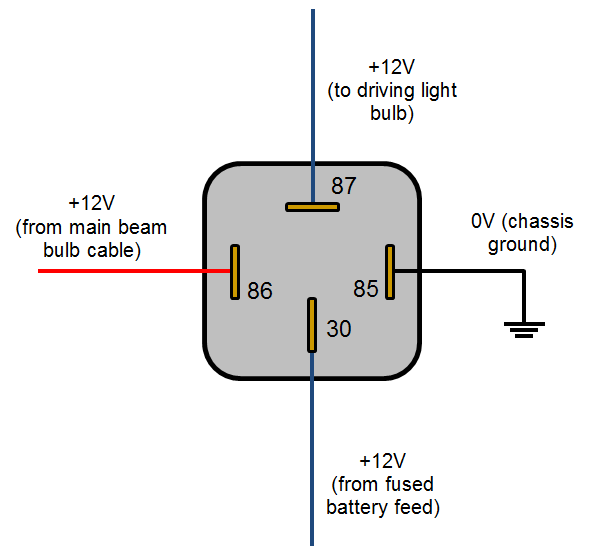
Connecting the earth from the switch to 85 and then passing a new proper earth to the LED would solve the problem, right? 30 and 86 can be the same source, a new fused wire. 87 would connect to the led. unless im talking nonsense, sorry have VERY basic knowledge of relays
Connecting the earth from the switch to 85 and then passing a new proper earth to the LED would solve the problem, right? 30 and 86 can be the same source, a new fused wire. 87 would connect to the led. unless im talking nonsense, sorry have VERY basic knowledge of relays
sierrafery
Well-Known Member
- Posts
- 17,910
- Location
- Arad/Romania
A relay doesnt solve the problem for the necessity of diode, you'll need diode anyway, it's even worst with relay cos the positive goes through it's coil to that circuit and it's higher load than a LED, it's simpler with blocking diode and LED directly, here's the sheme(i forgot to write +12V to the LED)

Similar threads
- Replies
- 11
- Views
- 663