Kenlow wiring mess

This site contains affiliate links for which LandyZone may be compensated if you make a purchase.

jwrw

Active Member
Posts
62
Hi, everyone.

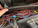
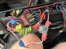
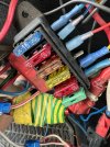
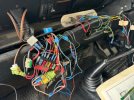
As far as I can tell a previous owner of our 110 (1986) was an avid collector of short lengths of wire in random colours, mostly red. They also had a large supply of fuses, connection blocks and insulation tape. At some point they decided to remove all the original wiring from the vehicle and replaced it with items from their collection.

My son and I are trying to unpick their work. We’ve removed several miles of unnecessary wire from under the seats, along with several redundant fuse boxes, and have been working back towards the original fuse box. Today we started unpicking the electrical spaghetti hidden behind the dashboard. It’s bad.

Anyway — I thought this was all going well but then realised that when I start the engine the Kenlow fan isn’t running. I’ve tried adjusting the thermostat across its whole range and it doesn’t come on.

Now I am trying to work out whether a) I’ve disturbed/disconnected something that has now broken it or b) the engine isn’t getting hot enough for it to come on. Or perhaps c) there is yet another secret fuse that has blown.

is there a test that will help me figure out whether I’ve broken it? Can I force it to come on?

Would you expect a Kenlow to come on with a cold engine?

The fan wiring disappears into a scary homemade loom where most of the wires change colour every 20cm so it is a real pain trying to trace it. I’ve got a phone/network wire tone tracing kit somewhere so that may be my next step.

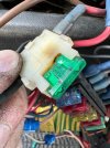
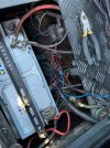
Thanks in advance. Pics attached for your amusement.
 

Attachments

  • IMG_2909.jpeg
    IMG_2909.jpeg
    172.6 KB · Views: 88
  • IMG_2908.jpeg
    IMG_2908.jpeg
    144.5 KB · Views: 89
  • IMG_2907.jpeg
    IMG_2907.jpeg
    173.7 KB · Views: 89
  • IMG_2912.jpeg
    IMG_2912.jpeg
    175.3 KB · Views: 86
  • IMG_2910.jpeg
    IMG_2910.jpeg
    137.8 KB · Views: 86
  • IMG_2913.jpeg
    IMG_2913.jpeg
    163.9 KB · Views: 92
Last edited:
Do you have a multi meter cos your gonna bloody need 1 🫣

The fan wiring shouldn’t be difficult to work out (with a meter;)) if you turn the sensor though it’s range I would expect it to come on at 1 end, if the engine was a little warm.

Personally I would start again with the fan and start your own wiring in a good way. Use black instead
:oops: for what you want to keep.

J
Thanks. Yes got a multimeter and also a basic car electrics probe thing.

I haven’t yet worked out how to test continuity from behind the dash to in the engine bay — the meter leads aren’t long enough! Is there a trick to that? Make up a long cable with croc clips on??

Yes I think you’re right about replacing the wiring back to the fan. Just wish I had a sensible place to wire it to!

(obviously I’m planning to use 240V earth sleeving for everything I replace, so future owners will know which parts are mine 🤪)
 
It’s like some kind of electrical nightmare.

This was the battery compartment before we started…
I’m certainly no auto-electrician, but the early Landies have some of the easiest “electrical systems” to work on of any car still in regular use. How and why the previous owners done what they did is baffling!
 
Thanks. Yes got a multimeter and also a basic car electrics probe thing.

I haven’t yet worked out how to test continuity from behind the dash to in the engine bay — the meter leads aren’t long enough! Is there a trick to that? Make up a long cable with croc clips on??

Yes I think you’re right about replacing the wiring back to the fan. Just wish I had a sensible place to wire it to!

(obviously I’m planning to use 240V earth sleeving for everything I replace, so future owners will know which parts are mine 🤪)

I wouldn't image there is any wiring in the cab area for the fan, (unless a bypass switch has been fitted)
To do a quick test on the fans should be as easy as applying a 12v supply and a ground at the fan connector (test only short period).

But it really sounds like you just have to just trace the wires from the fan to find probably a relay then see if that relay has a 12v supply.

With wiring like that it really is a case of removing a bit at a time of unwanted/unneeded. Or you rip the whole lot out and find a harness to give you a head start on all the standard stuff.

I have a similar issue as our little "mudball" was a ex police with LPG and so there are loads of unused/new wires. but nothing compared to what you have to deal with.

As for using a meter, yes sometimes some long "fly leads" can come in handy, but just checking continuity simple earth the wire you want to check then do the same with the meter at the other end, that way it don't matter how far apart they are.
Of course its easier if you actually have half an idea of which wire goes where, so good luck.

Final bit of advice, Keep the smoke in ;).

J
Thanks. Do you have any advice about what diameter of wire to use for replacements, please? Is there one specific gauge or something that is the 'right' choice for everything that ISN'T a high current connection? (although I appreciate that a fan could be a higher current)

I can't go by what's already installed because it includes everything from flimsy thin wires (like a cheap speaker connection or a doorbell) to old 240V mains flex and lots of sizes in between.

Smoke is still inside (apart from the burning oil coming out of the exhaust) although I think some of it has been trying to get out through the 30A fuse in one of my pics above. I don't think the holder is supposed to have that brownish patch.
 
Oh man, that is some birds nest.:eek: And your fan would Not come on with the Kenlow thermostat until the engine is warm. With engine warmed to normal running temp fan should come on at stats lowest setting.
 
Oh man, that is some birds nest.:eek: And your fan would Not come on with the Kenlow thermostat until the engine is warm. With engine warmed to normal running temp fan should come on at stats lowest setting.
Thanks. That's what I was wondering. I'm guessing it would be OK to go for a short drive to warm it up without knowing if the fan is working or not? No risk as long as I keep an eye on the temperature gauge, right?
 
Simple rule with vehile electrics:

Is is stock wiring if yes = Investigate and fix
Did Johnny Crimpset or Billy Block connector wire it? if yes = rip it out and wire it your self!
 
Last edited:
Thanks. Do you have any advice about what diameter of wire to use for replacements, please? Is there one specific gauge or something that is the 'right' choice for everything that ISN'T a high current connection? (although I appreciate that a fan could be a higher current)

Sorry I have no idea. As the fans come in different sizes/current draw. You don't give that info or even if you have 2 (unlikely but possible)
Trace back to the relay which may have a clue in its numbers, or look at the fan specs and check the Kenlow site.

Then somebody could help with cable sizing.

J
 
I see a heap of those horrible Scotch block connectors too. Second @Kissamyaura comment above.
As for wire size just look at wires into fan and use the same.
Fine to go for drive if temp gauge works. An IR temp reader is handy to check radiator/engine thermostat are doing their thing.
 
Sorry I have no idea. As the fans come in different sizes/current draw. You don't give that info or even if you have 2 (unlikely but possible)
Trace back to the relay which may have a clue in its numbers, or look at the fan specs and check the Kenlow site.

Then somebody could help with cable sizing.

J
Just one big fan. Thanks again -- will report back in due course...
 
I see a heap of those horrible Scotch block connectors too. Second @Kissamyaura comment above.
As for wire size just look at wires into fan and use the same.
Fine to go for drive if temp gauge works. An IR temp reader is handy to check radiator/engine thermostat are doing their thing.
Thanks. Yes, loads of Scotch block connectors. I think there's every kind of wire connector you could imagine. I'd love to know why they did it like this but I doubt I'll ever find out.

In that comment you mentioned above does crimpset mean those tubes where you push wires into them and squash the tube?

Will go for a drive and see if the fan comes on when it warms up a bit!
 
Plenty of wire size apps just enter voltage and length and expected draw for dc
Wiresizer on applestore free!!
Or google, 12v panet good source for wires n connectors
 
Hi, everyone.

As far as I can tell a previous owner of our 110 (1986) was an avid collector of short lengths of wire in random colours, mostly red. They also had a large supply of fuses, connection blocks and insulation tape. At some point they decided to remove all the original wiring from the vehicle and replaced it with items from their collection.

My son and I are trying to unpick their work. We’ve removed several miles of unnecessary wire from under the seats, along with several redundant fuse boxes, and have been working back towards the original fuse box. Today we started unpicking the electrical spaghetti hidden behind the dashboard. It’s bad.

Anyway — I thought this was all going well but then realised that when I start the engine the Kenlow fan isn’t running. I’ve tried adjusting the thermostat across its whole range and it doesn’t come on.

Now I am trying to work out whether a) I’ve disturbed/disconnected something that has now broken it or b) the engine isn’t getting hot enough for it to come on. Or perhaps c) there is yet another secret fuse that has blown.

is there a test that will help me figure out whether I’ve broken it? Can I force it to come on?

Would you expect a Kenlow to come on with a cold engine?

The fan wiring disappears into a scary homemade loom where most of the wires change colour every 20cm so it is a real pain trying to trace it. I’ve got a phone/network wire tone tracing kit somewhere so that may be my next step.

Thanks in advance. Pics attached for your amusement.

Oooofttt I hope you've got fire damage on your insurance, Id rip that lot out & start again.
 
It’s like some kind of electrical nightmare.

This was the battery compartment before we started…
That makes me very happy about the effort I went during my rebuild to fit an axillary fuse box and relay box into my battery compartment.

1724842328634.png


I invested in a proper barrel crimper so you can use "factory" brass crimp connectors rather than the red/blue/yellow crimps you see everywhere else. This is the tool that I have LINK with jaw H for open barrel crimps

I then just ordered a whole lot of the brass double barrel crimp connectors and the little insulated covers for them. I use a quick online tools to convert watts to amps for my lighting circuits, and knew from experience the twin fan setup I have needs 20amp on start up for each fan from when I was initially installing and it kept blowing fuses. It used less to run but has a spike to start.

I got my coloured wiring from this chap on ebay (LINK) as he did the normal colours and had enough that I could then use different colours for additional things which I then recorded for future use.
 
Last edited:
Thanks. That's what I was wondering. I'm guessing it would be OK to go for a short drive to warm it up without knowing if the fan is working or not? No risk as long as I keep an eye on the temperature gauge, right?
I am guessing as it is an '86 model that is either has an NA or a tdi conversion for the engine. Both of which will be fine with no fan for a short drive, the tdi even more so. I ran for a couple of years with no fan on my tdi with no issue watching the temp gauge.

Based on the state of everything else I would agree with the above of rip out and start again. To wiring in the fan is a fairly basic circuit with a low ampage (small cable) side with the thermostat switch, and a high ampage (large cable) side running to the fan itself and a relay in the middle. The easiest way of describing a relay circuit from when I was learning is to think of the circuit as a figure of 8. One loop is low power switching side which has the thermostat control and any override switch you may have, and the other loop is the high power side with the fan and the relay is the point they cross over in the middle.
 
I am guessing as it is an '86 model that is either has an NA or a tdi conversion for the engine. Both of which will be fine with no fan for a short drive, the tdi even more so. I ran for a couple of years with no fan on my tdi with no issue watching the temp gauge.
Yes, exactly right. It's a 200Tdi. Thanks, that's helpful.
Based on the state of everything else I would agree with the above of rip out and start again.
I agree. The hard bit is knowing where to start! It feels a bit all or nothing -- either I fiddle away with individual wires and try to replace them one at a time (which will get really messy with other existing wires in place), or I rip out everything and then add wires from scratch. I'd be more comfortable doing that if I had an idea of what it's supposed to be like.

I've got various wiring diagrams but of course they don't show you where the wires should actually run, or what gauge they should be, or what connectors they have on them. I'd love to find some photos of a decent job done by somebody who knew what they were doing.
To wiring in the fan is a fairly basic circuit with a low ampage (small cable) side with the thermostat switch, and a high ampage (large cable) side running to the fan itself and a relay in the middle. The easiest way of describing a relay circuit from when I was learning is to think of the circuit as a figure of 8. One loop is low power switching side which has the thermostat control and any override switch you may have, and the other loop is the high power side with the fan and the relay is the point they cross over in the middle.
Yes, that makes sense. But I don't really have much sense of what 'small cable' and 'large cable' means. All the wires at the moment are thin. But I looked at a calculator website which suggested that for 15A (purely a guess on my part -- that's half of the 30A fuse rating recommended by Kenlow) it would need 3mm or 4mm conductors -- which is at least 3x the size of anything installed at the moment!

Thanks again.
 
Back
Top