Northern Irelander
Well-Known Member
- Posts
- 2,890
- Location
- N. Ireland
Heres the DIY tools that help make life easy doing the hg repair, exclusive to this thread
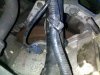
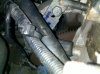
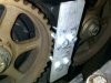
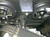
The flywheel locking tool bolts into the starter motor housing, sealey sell one for £35 +vat for all that it is
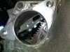
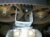
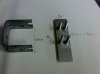
You only need the cam locking tool at the very end when placing on the belt. There are two types shown in the last attachment. A 10 x 10mm recess in a piece of metal strap interlocks the spokes on each sprocket.
the M5 bolt one interlocks the teeth from the two sprockets
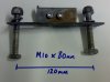
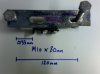
Dimensions are from the centre of each bolt hole.
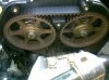
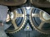
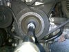
The two cam sprockets lined up (reading left to right from inlet cam to exhaust cam) <EXHAUST -O- IN> <EXHAUST -O- IN> are under low pressure from the valve springs. They tend not to move although the locking tool keeps it all in check,
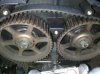
If you are removing the sprockets from the cams, a long metal bar with two M8 or M10 strategically placed at a distance of 80mm or so will interlock the cam spokes. This allows some counter leverage from the spanner/socket drive. Just wrap some tape around the two bolts to prevent fouling on the cams.
When the timing belt is replaced, tightened etc , remove all locking tools, rotate the crank several time by hand using the 22mm crank pulley nut. Re-allign the marks as before and re-check. sometimes the marks can be out by a tooth, apparently this is normal
Attached Thumbnails


The flywheel locking tool bolts into the starter motor housing, sealey sell one for £35 +vat for all that it is
You only need the cam locking tool at the very end when placing on the belt. There are two types shown in the last attachment. A 10 x 10mm recess in a piece of metal strap interlocks the spokes on each sprocket.
the M5 bolt one interlocks the teeth from the two sprockets
Dimensions are from the centre of each bolt hole.
The two cam sprockets lined up (reading left to right from inlet cam to exhaust cam) <EXHAUST -O- IN> <EXHAUST -O- IN> are under low pressure from the valve springs. They tend not to move although the locking tool keeps it all in check,
If you are removing the sprockets from the cams, a long metal bar with two M8 or M10 strategically placed at a distance of 80mm or so will interlock the cam spokes. This allows some counter leverage from the spanner/socket drive. Just wrap some tape around the two bolts to prevent fouling on the cams.
When the timing belt is replaced, tightened etc , remove all locking tools, rotate the crank several time by hand using the 22mm crank pulley nut. Re-allign the marks as before and re-check. sometimes the marks can be out by a tooth, apparently this is normal
Attached Thumbnails
") .
.