springwood
Member
- Posts
- 19
- Location
- Somerset
Hello, I'm a newbie and don't know my way around here ( actually I'm an oldbie and don't know my way around anywhere )
I am trying to complete a major transplant of a 96 3.9efi serpentine engine/ LT77 box into a 1986 Lotus. The job was started about 6 years ago and has passed through the hands of four owners since then. It is now down to me to finish it off.
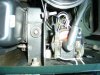
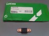
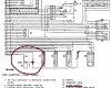
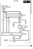
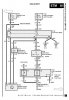
I realized that I am missing the wiring loom section which connects the distributor to the ignition amplifier. The plugs are 3 pin ( although only two used I think ) and oval in shape and seem to be very scarce.
Can anybody please point me towards someone who can help out here?
The male plug (ends ) are most important as the loom will need lengthening to about 40 inches.
Thanks in advance.
springwood.
I am trying to complete a major transplant of a 96 3.9efi serpentine engine/ LT77 box into a 1986 Lotus. The job was started about 6 years ago and has passed through the hands of four owners since then. It is now down to me to finish it off.
I realized that I am missing the wiring loom section which connects the distributor to the ignition amplifier. The plugs are 3 pin ( although only two used I think ) and oval in shape and seem to be very scarce.
Can anybody please point me towards someone who can help out here?
The male plug (ends ) are most important as the loom will need lengthening to about 40 inches.
Thanks in advance.
springwood.
")