- Posts
- 16,475
PART 1
Well, after replacing the Oil Pressure Switch it still leaked and considering it is still leaking despite my temporary attempt to stem the flow with Plumbers Mait Putty to tie me over until I could figure out where it was coming from....the Putty didnt work or I was putting it in the wrong place!
So I sourced a S/H front cover from the bay of E for £40, 3 month warranty and etc...I will still be checking the oil pump and replacing all relevant seals and O rings etc in any case cos yer never know..!!
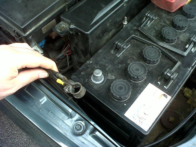
So to start, vehicle on ramps and disconnect the battery
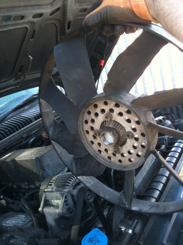
Then remove the viscous unit and fan....using Wammers method of a good sharp tap and bingo this is the first time this method has worked for me!!
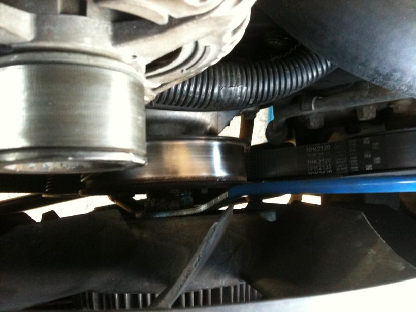
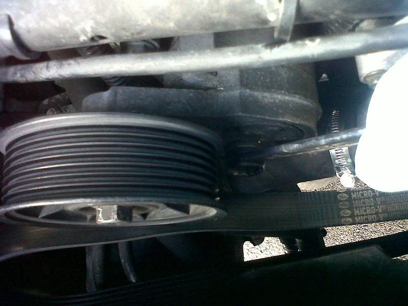
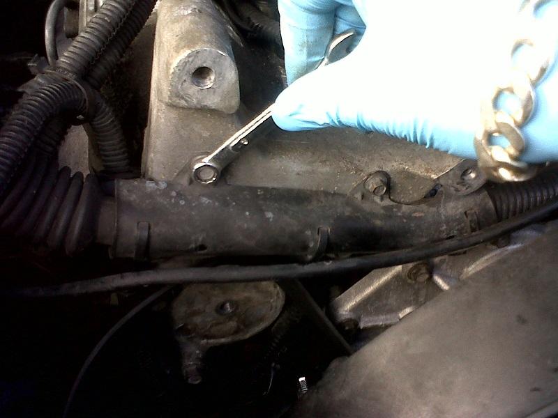
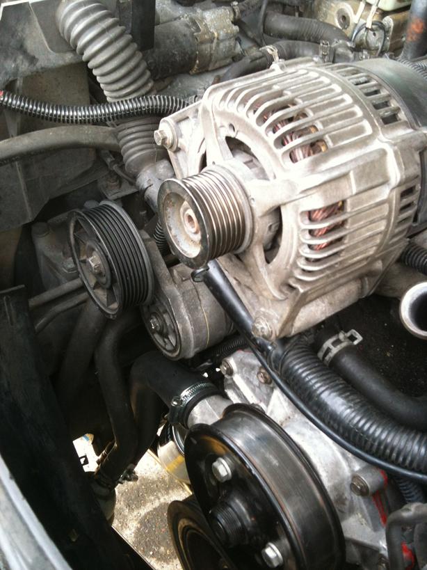
Using a 15mm spanner on the tensioner, turn inwards to loosen the drive belt
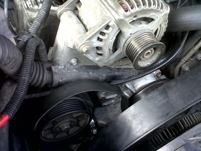
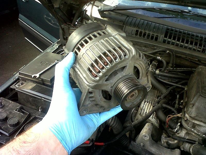
Then remove the Alternator Bolts and disconnect the wiring
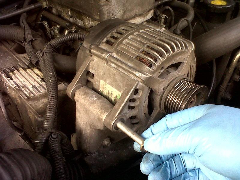
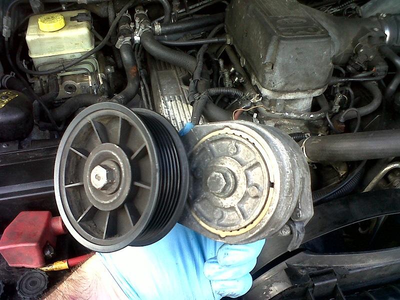
Next remove the tensioner assembly
Undo the wiring heatsheild, P clip on the side and the earth strap at the bottom
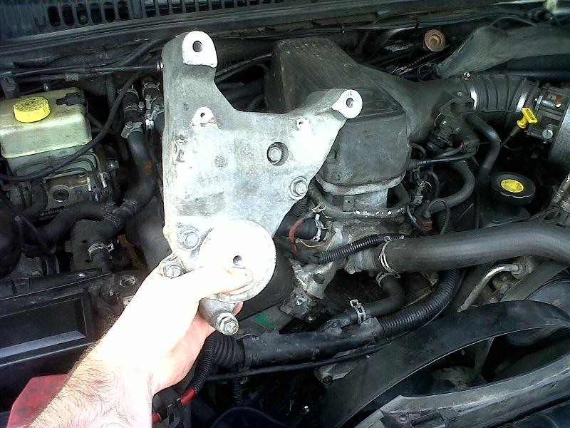
Undo the 4 bolts holding the Alternator Bracket on
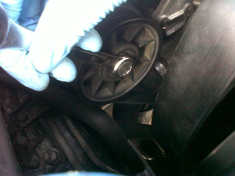
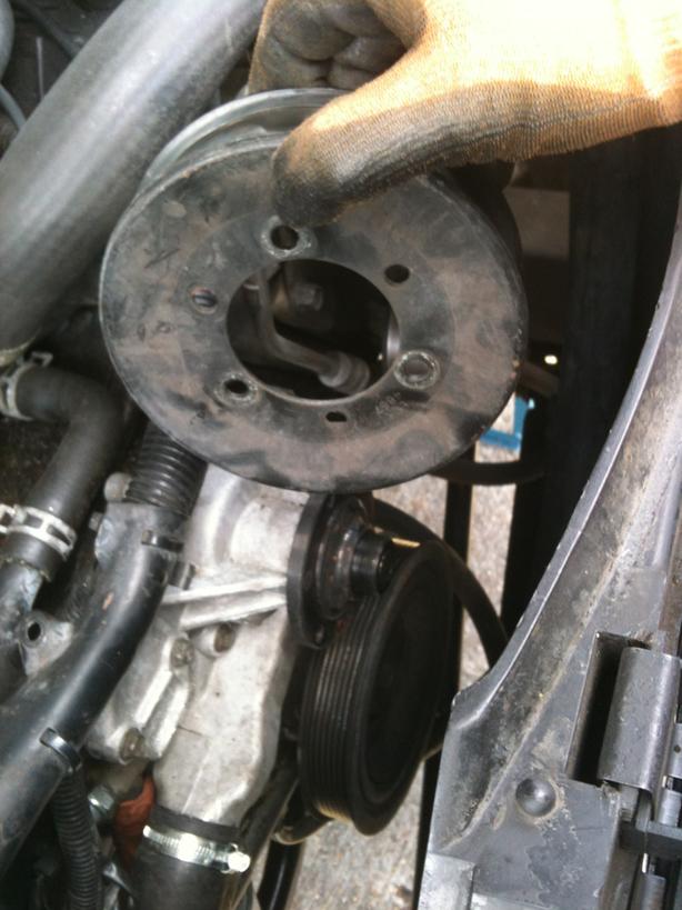
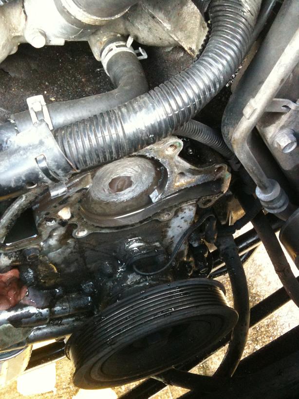
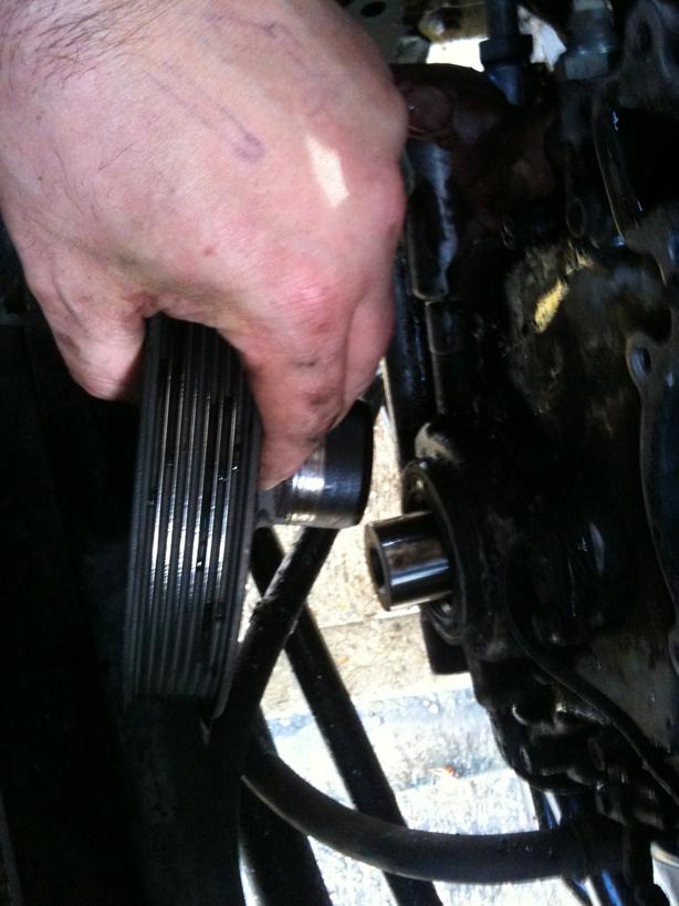
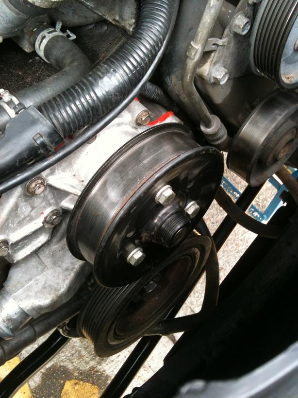
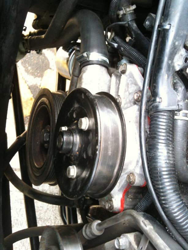
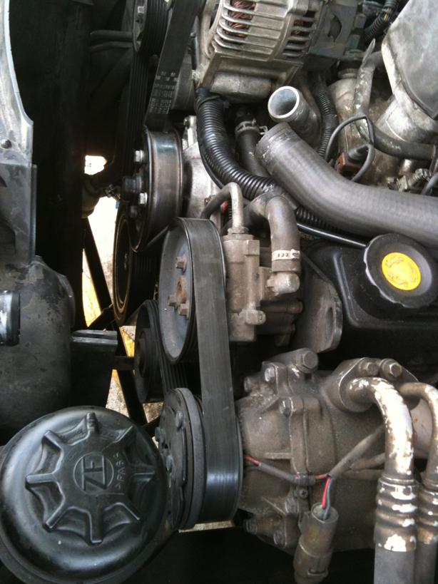
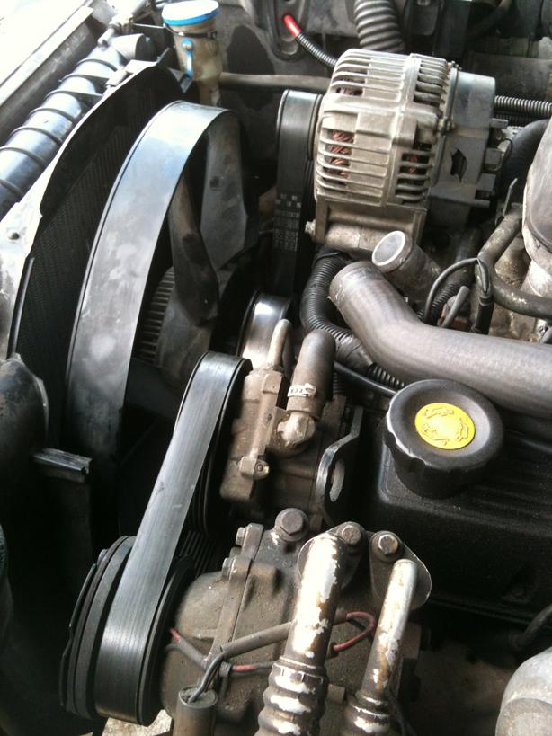
Next up, remove the water pump pulley
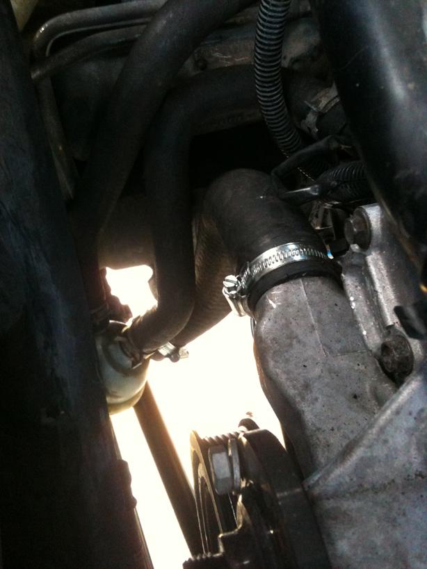
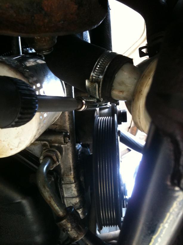
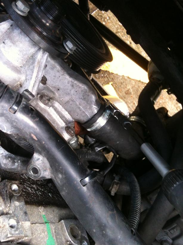
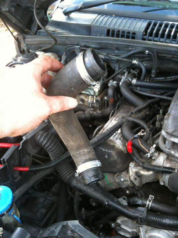
Next is time to drain the coolant from the rad and water pump, remove the lower rad hose from the stat housing and the water pump (I had already replaced those stupid spring clips with decent Jubilees)
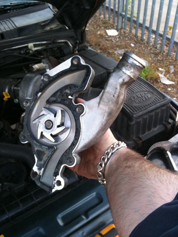
Undo the bolts holding the water pump on, note 3 of them are longer and are 11mm head not 10mm like the others!
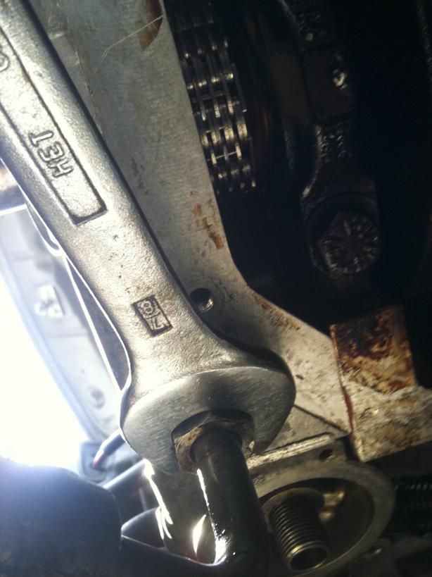
Now it is time to wrestle with the Crank Pulley Bolt or so I thought! This one undid are a couple of swift turns with my 2ft breaking bar...no need to hold the pulley using a special cranked tool...took me by surprise!
Undo the bolt holding the Camshaft Sensor plug in place and then also undo the Camshaft Hall Sensor itself, place this carefuly out of the way...they are sodding expensive!
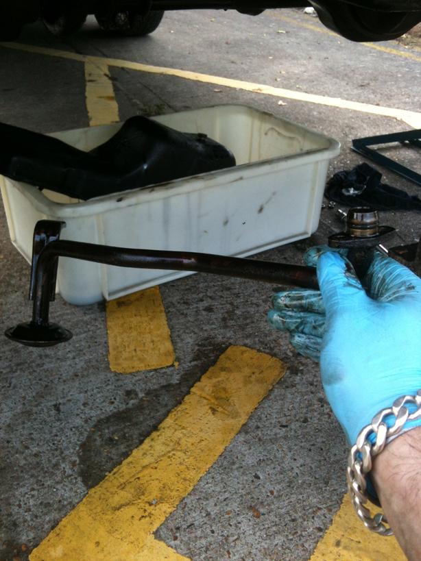
Time to start getting grubby and lying under the car! Time to drain the oil and remove the sump.
Suitable container and a 19mm spanner are the order of the day here!
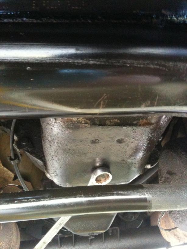
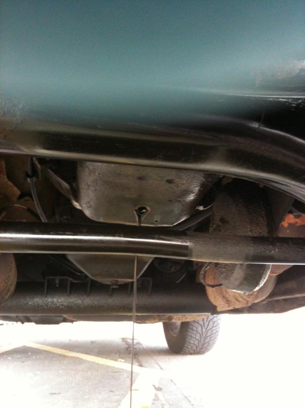
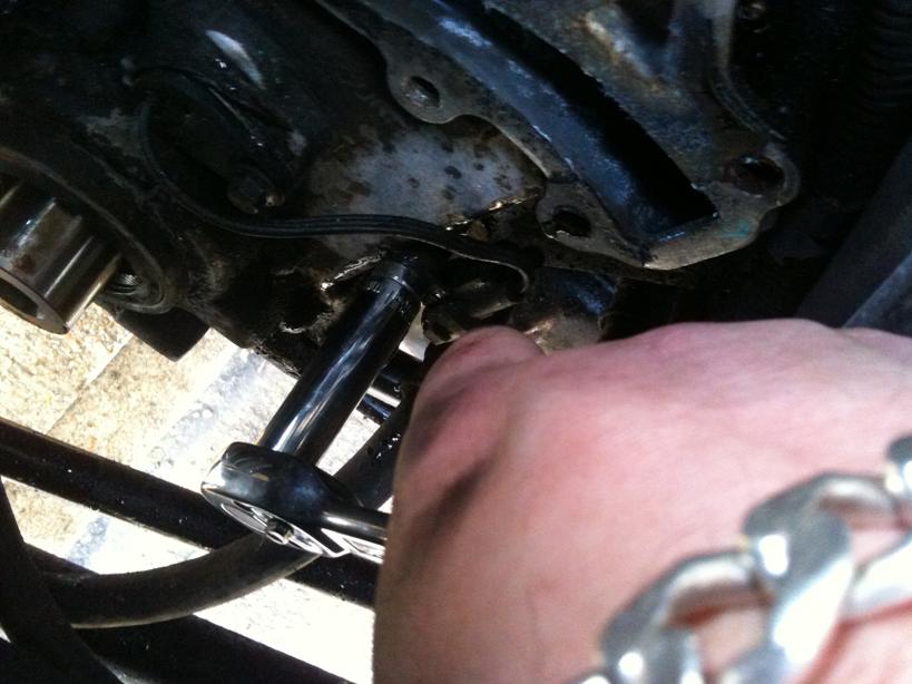
Time to crack open the sump....3 nuts on the timing cover and the rest are bolts...all 11mm hex heads....leave the 4 corner bolts in place once you have cracked them off, then remove the rest completely....
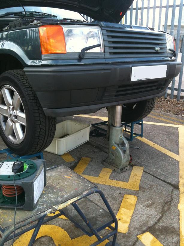
Now this is where I made a rookie mistake......I had driven up the ramps and lowered the car to access cos I thought even though I am 63 I will still need a step to reach over the slam panel, and I didnt want to stretch to much while under it....BUT, you cant get the sump out with the suspension down...so I used a 25ton top and toe jack on the front cross member to lift the vehicle up off the bumps so I could remove the sump....
OK Sump off...
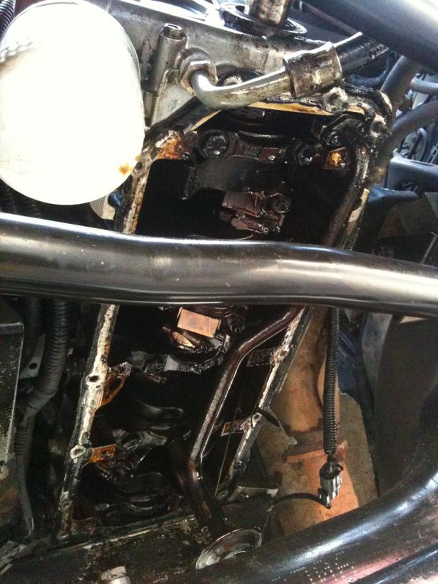
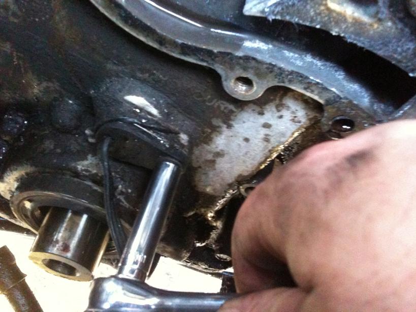
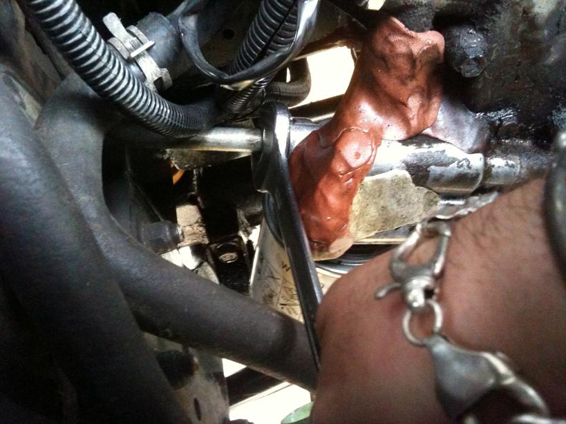
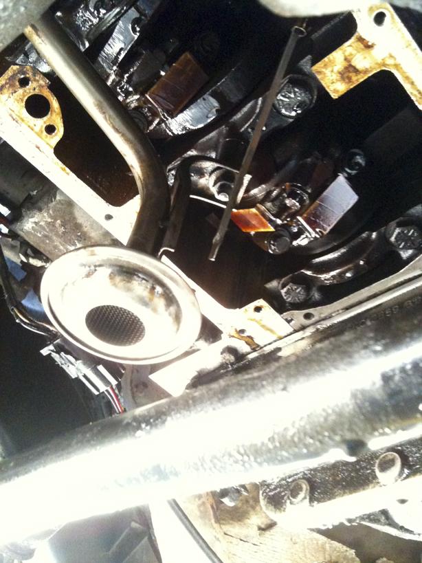
Next up is to remove the Oil Pick Up Strainer....simple 2x 8mm head bolts at one end and a 11mm nut at the strainer end
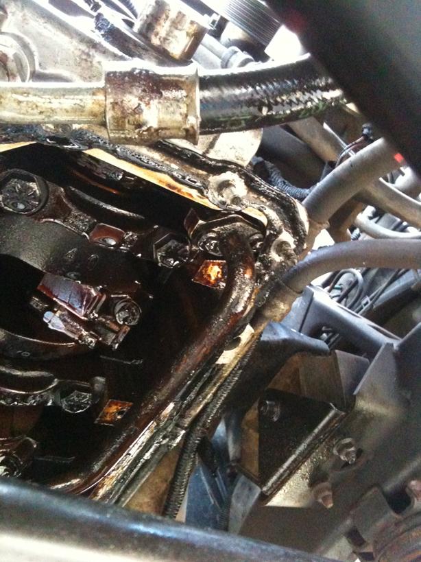
(Now ignore the Plumbers Putty I used as a temporary fix that failed miserably I used it to try and stem the leak while I was waiting for the new front cover to arrive)
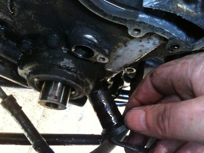
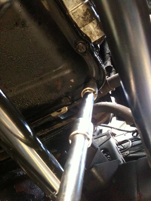
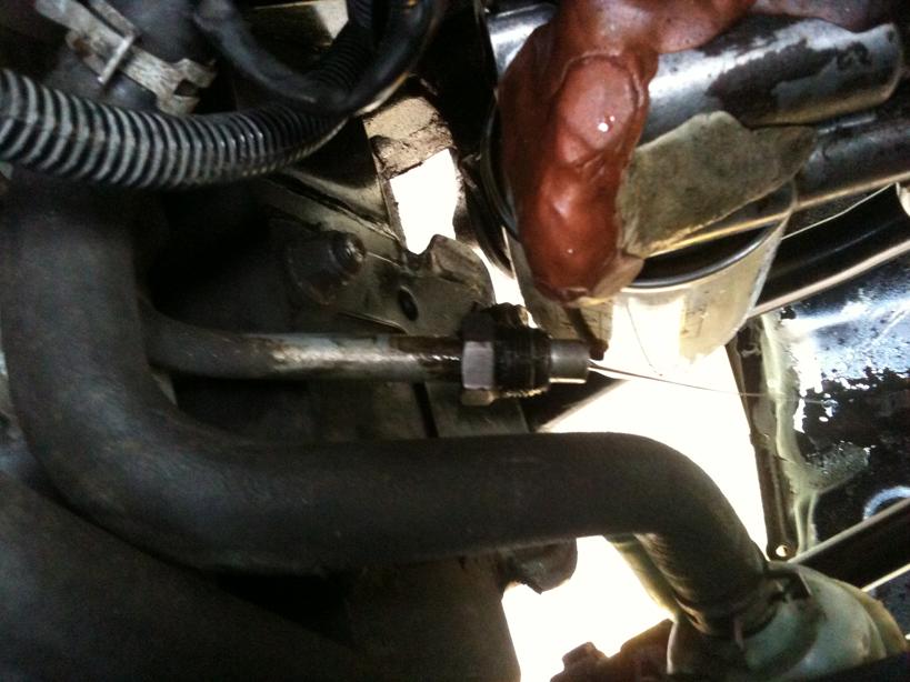
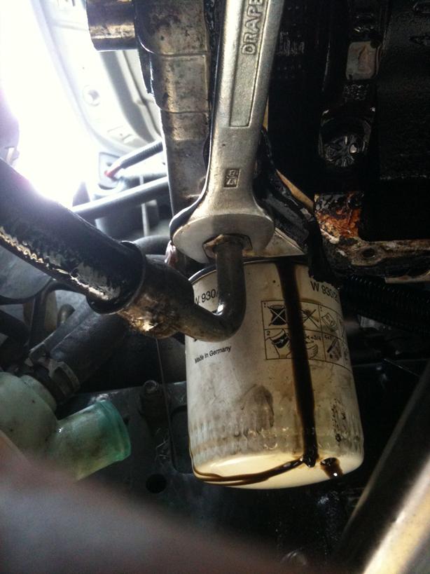
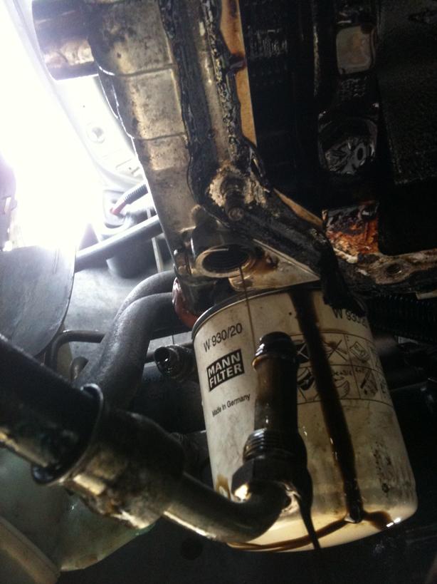
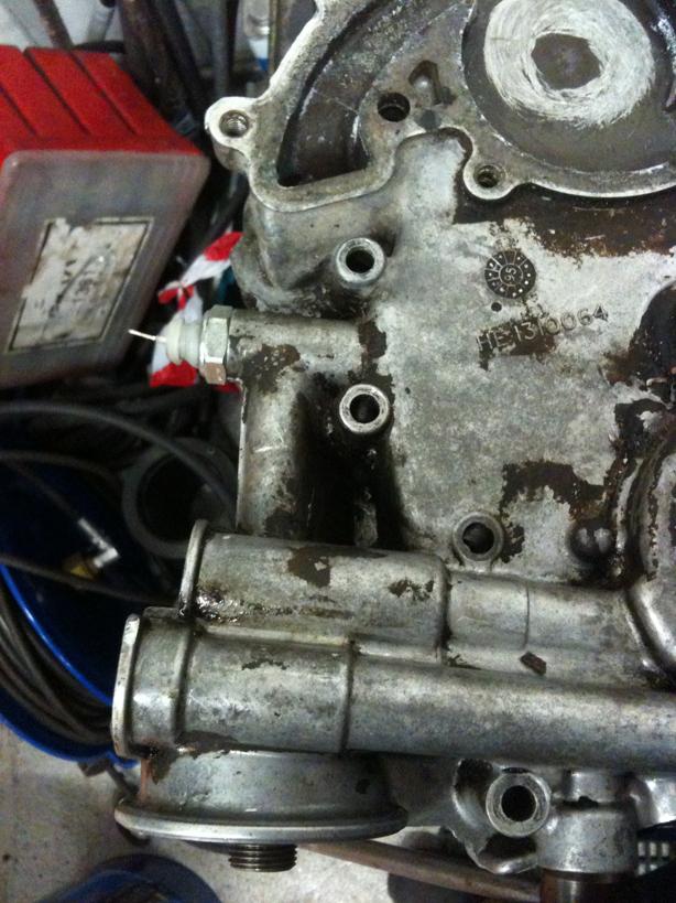
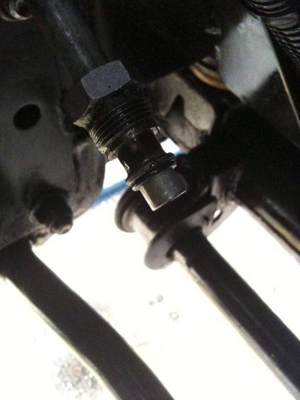
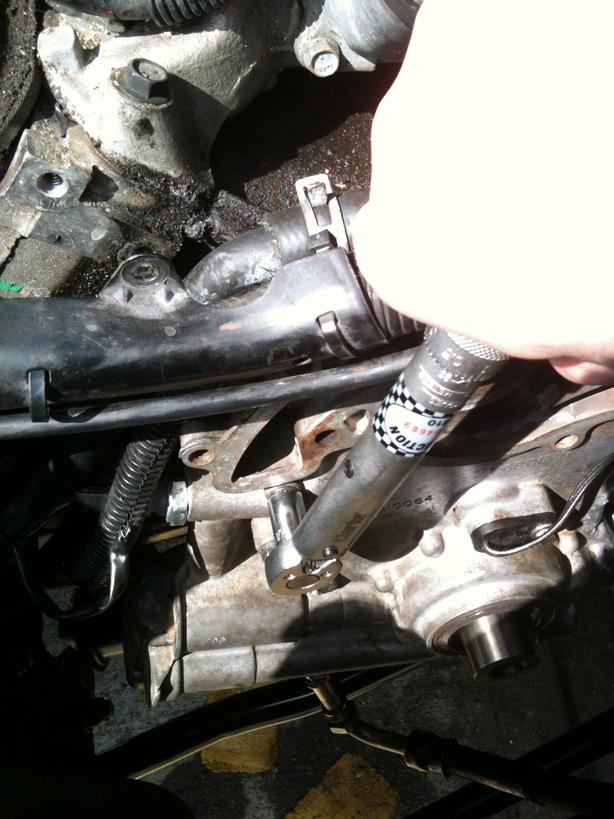
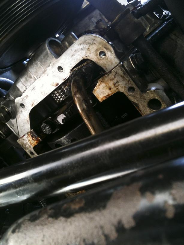
7/8 Oil Pipe Unions, 2 off, one on the underside and one on the side under the Oil Pressure Switch, undo these, and do so carefully so you dont round off the unions, Parker Pipe Spanners are great for this job but I aint got that kinda cash so an open 7/8 spanner used carefully will do!
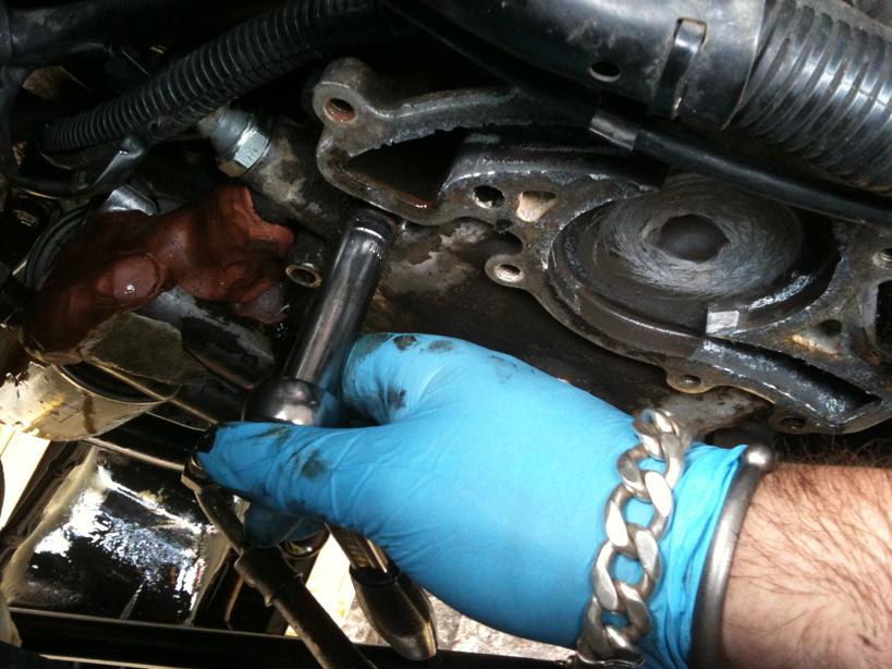
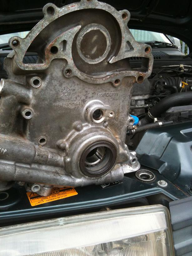
Now time to undo the Front Timing Chain Cover Bolts....and a little tap to break the seal and off she comes. It is located on dowels so dont tap downwards...
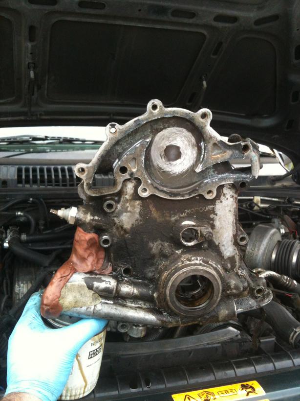
So covers off...time to clean it up in the spirit washer and chip off the repair putty....
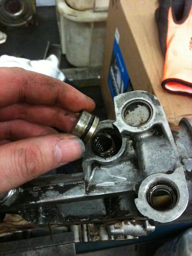
Looking at it, I couldnt see any cracks, but the pressure relief valve that sits behind the circlip and covered by the cap could be pressed in under moderate finger pressure...to me that isnt right, so I decided to dismantle the relief valve.
Remove the circlip while covering the cap as it is under spring pressure, mine was a bit stuck so a screwdriver up the hole by the oil filter (you should be able to see the spring) and a quick poke on the spring loosened the cap and O ring...
Then the spring (part of the refitment is to measure the free length of the spring to ensure correct relief valve pressure setting)
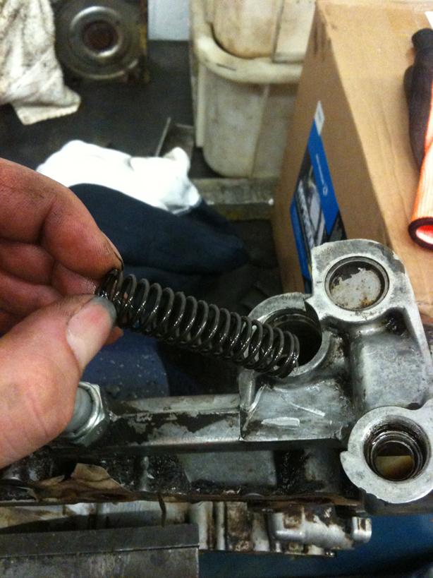
Spacer tube
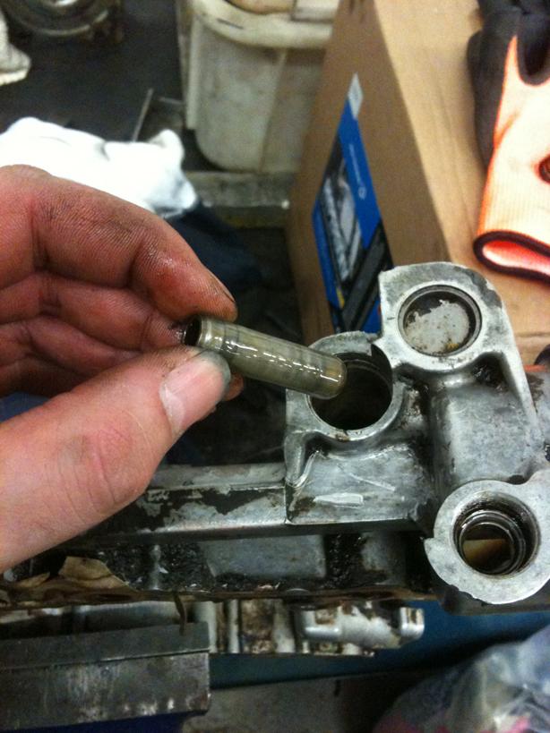
Valve (on the end of a magnetic prodder!)
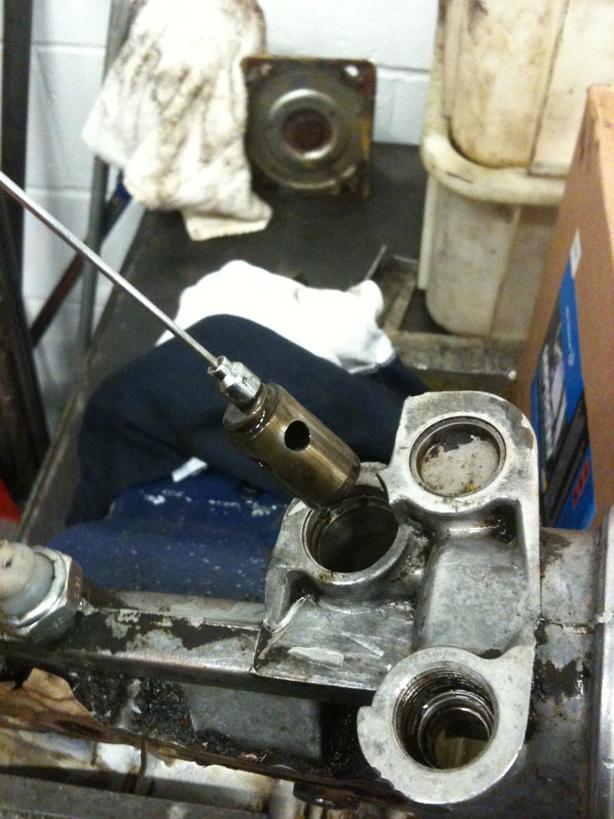
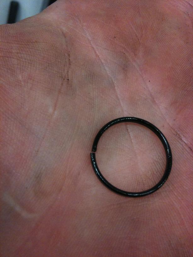
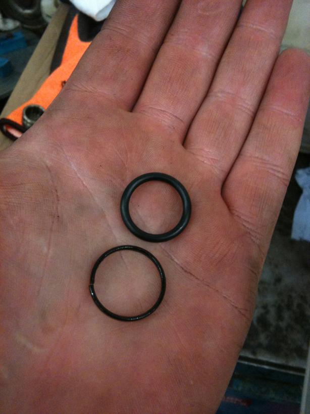
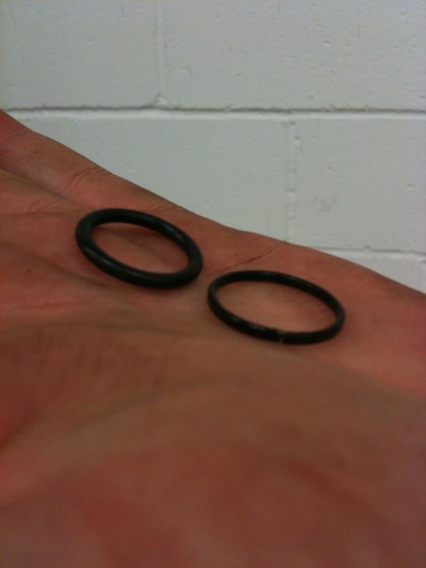
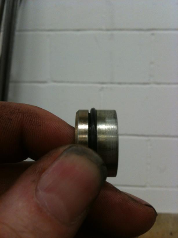
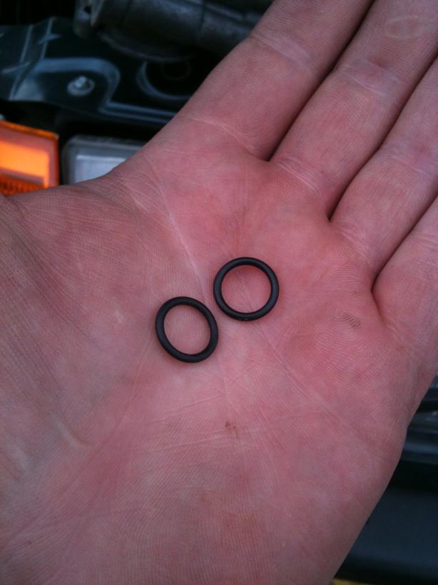
Now it is apart, I think I have found the probable cause... the relief valve cap O ring is in a poor state...totally flat, rock solid and brittle....
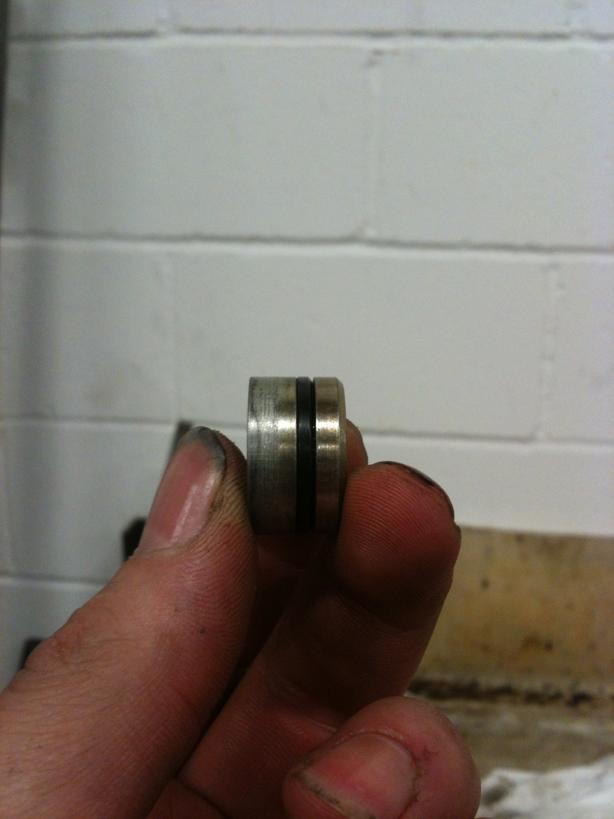
Pictured with a new O Ring (19x1.5 Viton is best due to the high temps)
Whilst this is the most likely cause of the leak, I will be fitting a S/H refurbed cover, as I am not 100% confident the original cover doesnt have a leak/crack in it...and for £40, I may aswell change it over.
Now I have the cover off, now is a good time to replace the timing chain, for the sake of new sprockets and chain costing around £25-30 I may as well while it is apart!
Will be doing a Part 2 of this How To which covers the clean up of the mating faces, fitting the Chain and Sprockets, and refitting the cover and gaskets etc....
PART 2
Following on from Part 1 http://www.landyzone.co.uk/lz/f10/gems-front-timing-chain-cover-part-1-a-260980.html
So, carrying on from where I left off....
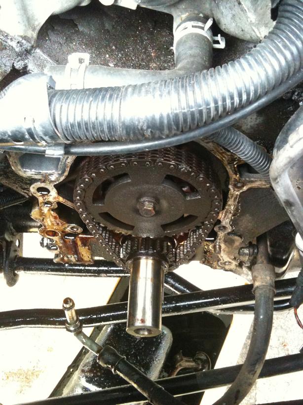
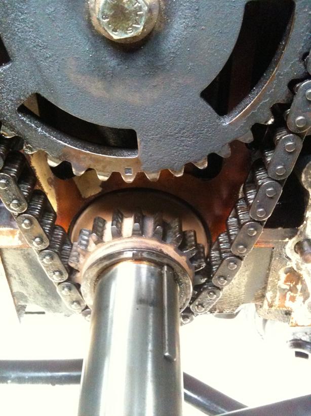
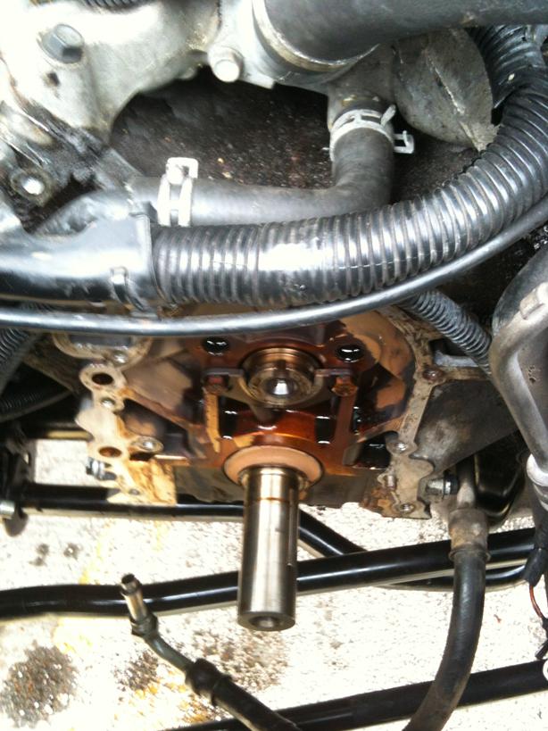
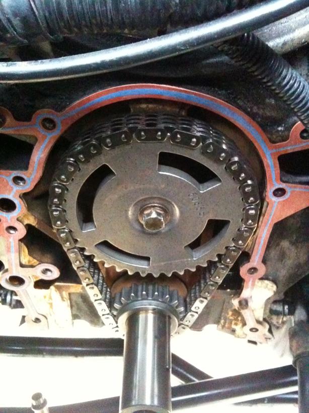
The front cover is off exposing the timing gears and chain, first align the timing gears, they should have a dimple mark on them to line them up
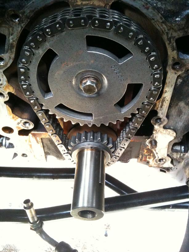
Considering I am replacing the timing gears and chain as mine were old and a little slack, I wedged a screwdriver in the crank sprocket against the chain to lock it in place while I cracked the Camshaft bolt off...if you are to refit the same set, it would be best to restrain the crank by refitting the pulley and fitting the pulley holding tool (more about this tool later!)
With some gentle pulling and wiggling, remove the timing chain and sprockets...careful not to move the crank or cam while doing this!
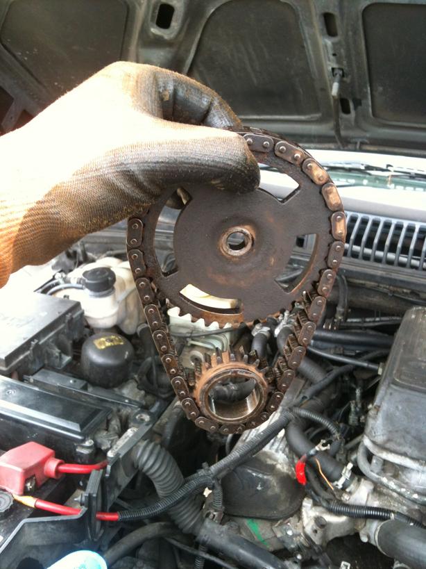
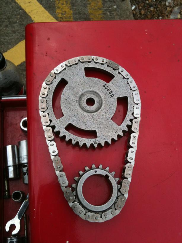
Lay the new sprockets and chain down and line up the timing marks and put the chain round ensuring they stay aligned.
Slide them on to the crank and camshaft as an assembly and torque the camshaft bolt to the specifications in RAVE
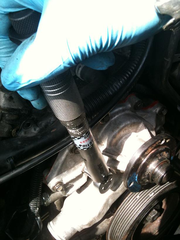
Time to prep the replacement front cover....knock out the old seal and the official procedure is to fit the front cover to the engine then put the seal in place and slide a special tool over the end of the crank shaft and press the seal into place...
Not having the special tool and it not being strictly necessary, before you remove the original seal, look to see how deep it seats in the cover and then using a press and a large socket or similar, gently press the new seal in square to the right depth.
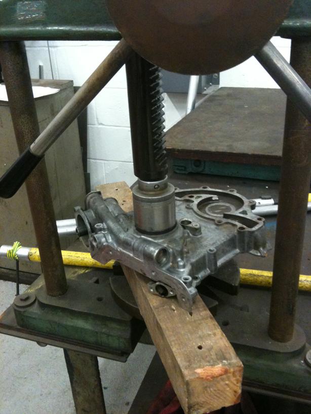
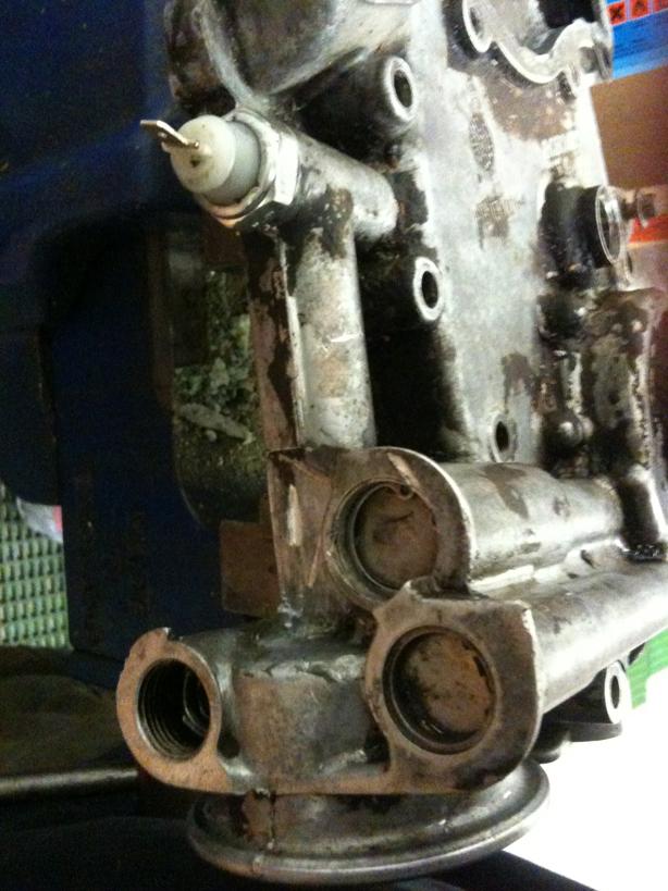
Replace the O rings that fit on to the Oil Cooler unions, lube with clean oil or Vaseline first!
Clean the mating face and fit a new gasket
Fit the front cover over the mounting dowels and fit the bolts. Torque to the required specification....I like to torque bolts for 2 reason...1) RAVE says so and 2) the parts are cast/machine aluminium and can crack or strip if over tightened.
Fit the cooler unions note, dont over tighten them as you can crack the front cover if over torque...I dont own any Crows Foot ratchet heads so I couldnt torque these so I used a good guesstimate.
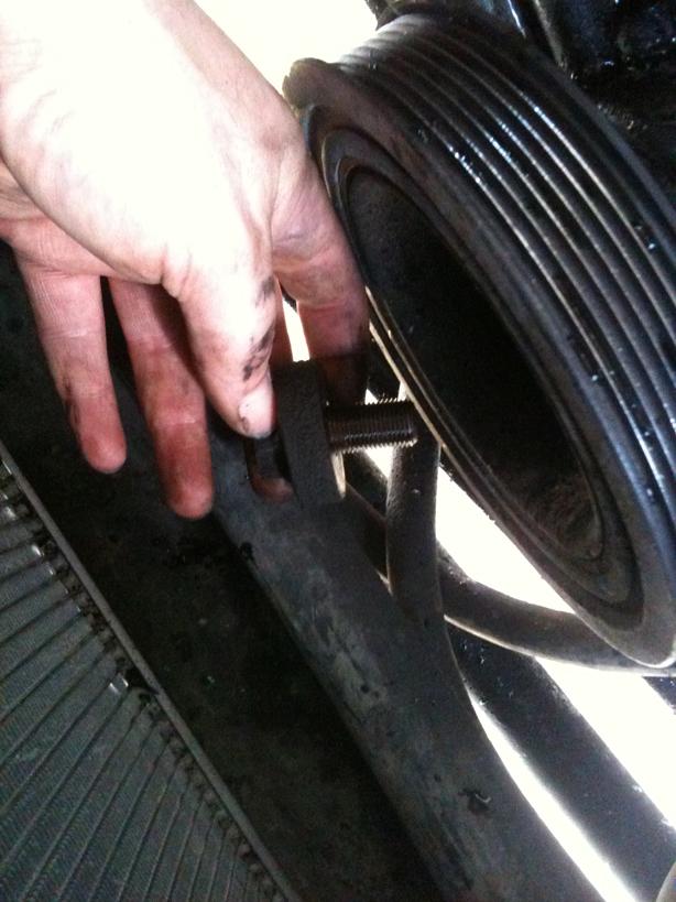
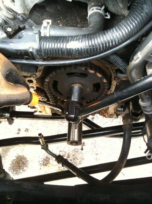
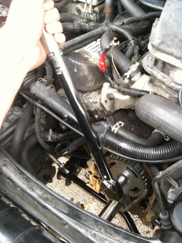
Now, time to fit the Crank Pulley. Mine came off far too easily when you consider the bolt is suppose to be torque to 270Nm (200lb whatsits) so I fabricated a tool to hold the crank pulley in place while torquing it up correctly.
The Disc is 89mm diameter with two 8.5mm holes drilled at 74mm centres directly opposed and the centre hole is 2 (50.4mm) diameter, one of our machinists kindly made the disc for me!
I then (badly) welded the 20mm box to it as a handle about 16 long!
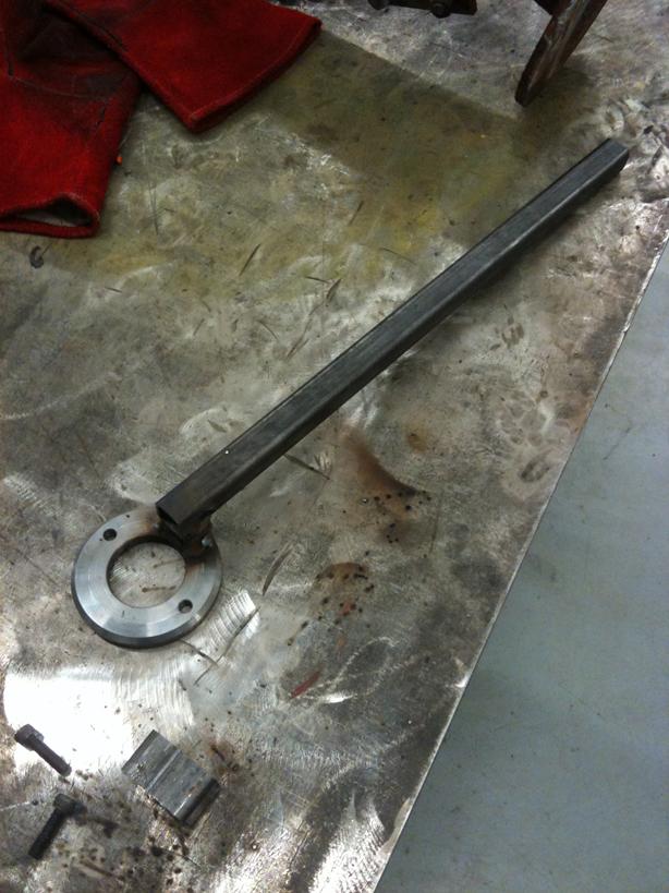
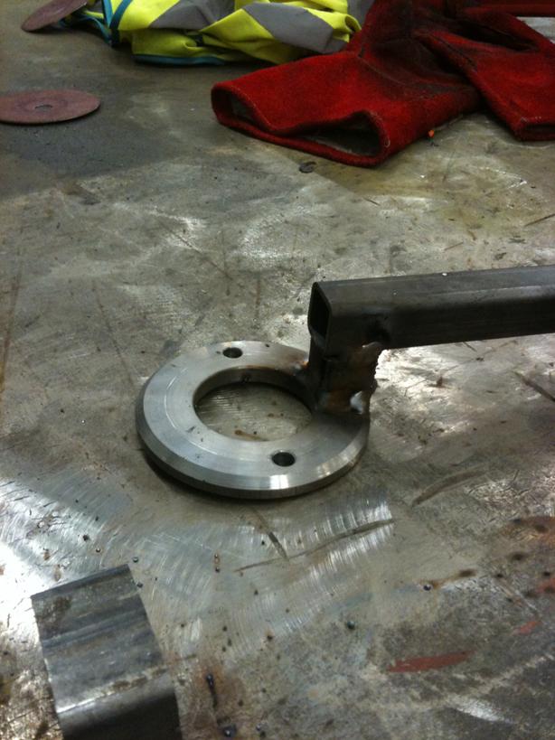
This then bolts to the crank pulley using 5/16 UNC Socket Caps M8 would be seen to fit but the thread pitch is slightly different and will bind up after a few turns....stick to 5/16 UNC unless really in the ****e!
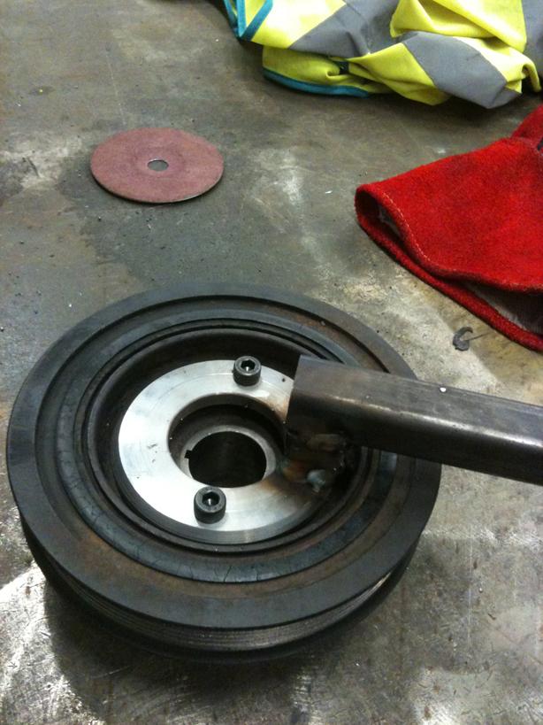
Fit the crank pulley and fit the tool, then torque the bolt correctly.
Next clean the water pump mating faces and fit a new gasket, I always like to smear a tiny amount of liquid gasket sealant in addition to the paper gasket, not strictly necessary, but I do it!
Fit the water pump and again torque the bolts on fitment, remember 3 are longer than the others so get them in the right place!
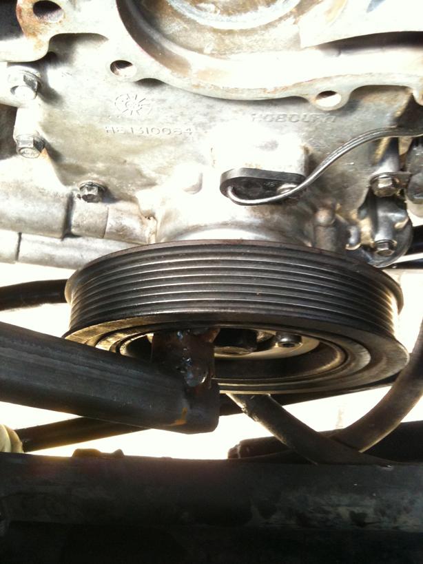
Fit the pulley and torque up...
Time to fit the Oil Pick Up and Sump. Clean up the sump mating faces and fit a new gasket...the one I got was a rubber gasket, I smeared some gasket sealant on the sump and laid the rubber gasket on top, the sealant holds it in place while you refit! (forgot to take pictures of the sump in place!)
I fitted a new bottom hose as the original looked past its best, and fitted a fresh oil filter. Smear the filter seal with clean oil before fitting.
It Alternator Bracket, Wiring Heat Shield, Earth Strap and P Clip. Then the Alternator and Belt tensioner.
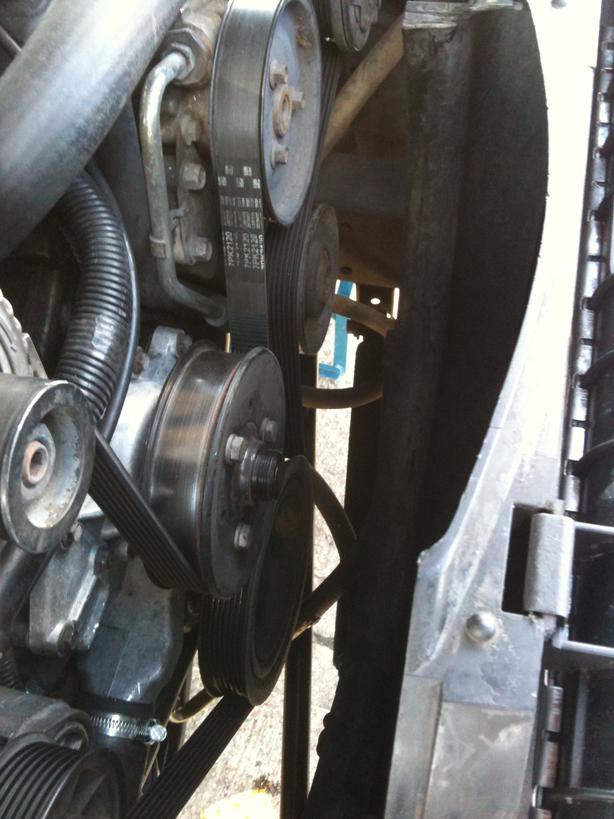
Refit the serpentine belt
Refit viscous fan and shroud, fill with clean oil and fresh coolant. Reconnect battery and resync the keys. Then start the car....and after a few rattles as things get lubed up and the hydraulic lifters reprime with oil and BINGO...job done....
Well, after replacing the Oil Pressure Switch it still leaked and considering it is still leaking despite my temporary attempt to stem the flow with Plumbers Mait Putty to tie me over until I could figure out where it was coming from....the Putty didnt work or I was putting it in the wrong place!
So I sourced a S/H front cover from the bay of E for £40, 3 month warranty and etc...I will still be checking the oil pump and replacing all relevant seals and O rings etc in any case cos yer never know..!!
So to start, vehicle on ramps and disconnect the battery
Then remove the viscous unit and fan....using Wammers method of a good sharp tap and bingo this is the first time this method has worked for me!!
Using a 15mm spanner on the tensioner, turn inwards to loosen the drive belt
Then remove the Alternator Bolts and disconnect the wiring
Next remove the tensioner assembly
Undo the wiring heatsheild, P clip on the side and the earth strap at the bottom
Undo the 4 bolts holding the Alternator Bracket on
Next up, remove the water pump pulley
Next is time to drain the coolant from the rad and water pump, remove the lower rad hose from the stat housing and the water pump (I had already replaced those stupid spring clips with decent Jubilees)
Undo the bolts holding the water pump on, note 3 of them are longer and are 11mm head not 10mm like the others!
Now it is time to wrestle with the Crank Pulley Bolt or so I thought! This one undid are a couple of swift turns with my 2ft breaking bar...no need to hold the pulley using a special cranked tool...took me by surprise!
Undo the bolt holding the Camshaft Sensor plug in place and then also undo the Camshaft Hall Sensor itself, place this carefuly out of the way...they are sodding expensive!
Time to start getting grubby and lying under the car! Time to drain the oil and remove the sump.
Suitable container and a 19mm spanner are the order of the day here!
Time to crack open the sump....3 nuts on the timing cover and the rest are bolts...all 11mm hex heads....leave the 4 corner bolts in place once you have cracked them off, then remove the rest completely....
Now this is where I made a rookie mistake......I had driven up the ramps and lowered the car to access cos I thought even though I am 63 I will still need a step to reach over the slam panel, and I didnt want to stretch to much while under it....BUT, you cant get the sump out with the suspension down...so I used a 25ton top and toe jack on the front cross member to lift the vehicle up off the bumps so I could remove the sump....
OK Sump off...
Next up is to remove the Oil Pick Up Strainer....simple 2x 8mm head bolts at one end and a 11mm nut at the strainer end
(Now ignore the Plumbers Putty I used as a temporary fix that failed miserably I used it to try and stem the leak while I was waiting for the new front cover to arrive)
7/8 Oil Pipe Unions, 2 off, one on the underside and one on the side under the Oil Pressure Switch, undo these, and do so carefully so you dont round off the unions, Parker Pipe Spanners are great for this job but I aint got that kinda cash so an open 7/8 spanner used carefully will do!
Now time to undo the Front Timing Chain Cover Bolts....and a little tap to break the seal and off she comes. It is located on dowels so dont tap downwards...
So covers off...time to clean it up in the spirit washer and chip off the repair putty....
Looking at it, I couldnt see any cracks, but the pressure relief valve that sits behind the circlip and covered by the cap could be pressed in under moderate finger pressure...to me that isnt right, so I decided to dismantle the relief valve.
Remove the circlip while covering the cap as it is under spring pressure, mine was a bit stuck so a screwdriver up the hole by the oil filter (you should be able to see the spring) and a quick poke on the spring loosened the cap and O ring...
Then the spring (part of the refitment is to measure the free length of the spring to ensure correct relief valve pressure setting)
Spacer tube
Valve (on the end of a magnetic prodder!)
Now it is apart, I think I have found the probable cause... the relief valve cap O ring is in a poor state...totally flat, rock solid and brittle....
Pictured with a new O Ring (19x1.5 Viton is best due to the high temps)
Whilst this is the most likely cause of the leak, I will be fitting a S/H refurbed cover, as I am not 100% confident the original cover doesnt have a leak/crack in it...and for £40, I may aswell change it over.
Now I have the cover off, now is a good time to replace the timing chain, for the sake of new sprockets and chain costing around £25-30 I may as well while it is apart!
Will be doing a Part 2 of this How To which covers the clean up of the mating faces, fitting the Chain and Sprockets, and refitting the cover and gaskets etc....
PART 2
Following on from Part 1 http://www.landyzone.co.uk/lz/f10/gems-front-timing-chain-cover-part-1-a-260980.html
So, carrying on from where I left off....
The front cover is off exposing the timing gears and chain, first align the timing gears, they should have a dimple mark on them to line them up
Considering I am replacing the timing gears and chain as mine were old and a little slack, I wedged a screwdriver in the crank sprocket against the chain to lock it in place while I cracked the Camshaft bolt off...if you are to refit the same set, it would be best to restrain the crank by refitting the pulley and fitting the pulley holding tool (more about this tool later!)
With some gentle pulling and wiggling, remove the timing chain and sprockets...careful not to move the crank or cam while doing this!
Lay the new sprockets and chain down and line up the timing marks and put the chain round ensuring they stay aligned.
Slide them on to the crank and camshaft as an assembly and torque the camshaft bolt to the specifications in RAVE
Time to prep the replacement front cover....knock out the old seal and the official procedure is to fit the front cover to the engine then put the seal in place and slide a special tool over the end of the crank shaft and press the seal into place...
Not having the special tool and it not being strictly necessary, before you remove the original seal, look to see how deep it seats in the cover and then using a press and a large socket or similar, gently press the new seal in square to the right depth.
Replace the O rings that fit on to the Oil Cooler unions, lube with clean oil or Vaseline first!
Clean the mating face and fit a new gasket
Fit the front cover over the mounting dowels and fit the bolts. Torque to the required specification....I like to torque bolts for 2 reason...1) RAVE says so and 2) the parts are cast/machine aluminium and can crack or strip if over tightened.
Fit the cooler unions note, dont over tighten them as you can crack the front cover if over torque...I dont own any Crows Foot ratchet heads so I couldnt torque these so I used a good guesstimate.
Now, time to fit the Crank Pulley. Mine came off far too easily when you consider the bolt is suppose to be torque to 270Nm (200lb whatsits) so I fabricated a tool to hold the crank pulley in place while torquing it up correctly.
The Disc is 89mm diameter with two 8.5mm holes drilled at 74mm centres directly opposed and the centre hole is 2 (50.4mm) diameter, one of our machinists kindly made the disc for me!
I then (badly) welded the 20mm box to it as a handle about 16 long!
This then bolts to the crank pulley using 5/16 UNC Socket Caps M8 would be seen to fit but the thread pitch is slightly different and will bind up after a few turns....stick to 5/16 UNC unless really in the ****e!
Fit the crank pulley and fit the tool, then torque the bolt correctly.
Next clean the water pump mating faces and fit a new gasket, I always like to smear a tiny amount of liquid gasket sealant in addition to the paper gasket, not strictly necessary, but I do it!
Fit the water pump and again torque the bolts on fitment, remember 3 are longer than the others so get them in the right place!
Fit the pulley and torque up...
Time to fit the Oil Pick Up and Sump. Clean up the sump mating faces and fit a new gasket...the one I got was a rubber gasket, I smeared some gasket sealant on the sump and laid the rubber gasket on top, the sealant holds it in place while you refit! (forgot to take pictures of the sump in place!)
I fitted a new bottom hose as the original looked past its best, and fitted a fresh oil filter. Smear the filter seal with clean oil before fitting.
It Alternator Bracket, Wiring Heat Shield, Earth Strap and P Clip. Then the Alternator and Belt tensioner.
Refit the serpentine belt
Refit viscous fan and shroud, fill with clean oil and fresh coolant. Reconnect battery and resync the keys. Then start the car....and after a few rattles as things get lubed up and the hydraulic lifters reprime with oil and BINGO...job done....
Last edited: