55FM58
Member
- Posts
- 48
- Location
- Dagenham, Essex
Having finally managed to rebuild a 24v blower units for my S3 FFR and getting it to fit under the wing in the correct spot it came time to check it out. First problem was found when, having temporarily connected the wires under the bonnet nothing happened. Checking the Brown/Orange feed wire to the switch got a reading of 0v instead of the expected 24v whilst at the ignition switch end there was 24v. Seemed odd so I went and had a look at the wiring diagram and found there was an in-line fuse in the feed. Rain then stopped play until today.
We actually had a dry spell today for the first time since Sat afternoon - so I nipped out fast to the Landie. Found the in-line fuse for the heater fan - what a stupid place to locate it under the inner dash pod - and mangled the hands cracking the holder open and fitting a new 35A glass cartridge fuse. You'd think the lead from the out side of the fuse holder to the switch would go direct to the switch but no - it seems to go in a taped section of the loom first so you cannot pull the fuse holder out from under the pod.
Once it was in and the holder done up again I checked power at the switch end of the Brown/Orange feed and had 24v. Connected it and turned on the switch - nothing. Popped the bonnet and found I'd forgotten to reconnect the 2 leads from the vehicle into the double female bullet connector - did the ones from the fan motor but not the vehicle side.. Once they were plugged in, I turned power on and the fan started.
With the switch in the off position!!
Flicking it to the on-1 and on-2 positions just turned the fan off. I think the switch might be wired incorrectly.")
It's as it came with the vehicle so I had no reason till now to question the connections.
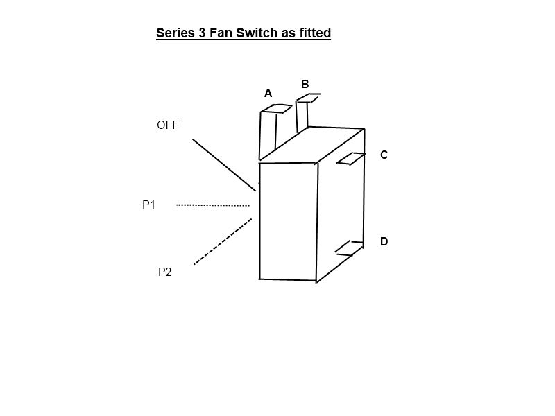
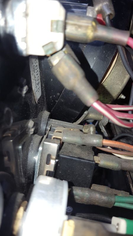
Basically there are two male terminals at the top of the switch - the power in lead goes to the R/H one of these. I tried it on the L/H side too - no change, Then there are two male terminals projecting from the back of the switch with the Green/Yellow and Green/Brown leads on that go to the fan motor.
Does anyone know how this switch is actually meant to be connected as I cannot get the dash out far enough to run connectivity checks with a multimeter, nor can I get the switch out of the dash without risk of damage to the dash.
We actually had a dry spell today for the first time since Sat afternoon - so I nipped out fast to the Landie. Found the in-line fuse for the heater fan - what a stupid place to locate it under the inner dash pod - and mangled the hands cracking the holder open and fitting a new 35A glass cartridge fuse. You'd think the lead from the out side of the fuse holder to the switch would go direct to the switch but no - it seems to go in a taped section of the loom first so you cannot pull the fuse holder out from under the pod.
Once it was in and the holder done up again I checked power at the switch end of the Brown/Orange feed and had 24v. Connected it and turned on the switch - nothing. Popped the bonnet and found I'd forgotten to reconnect the 2 leads from the vehicle into the double female bullet connector - did the ones from the fan motor but not the vehicle side.. Once they were plugged in, I turned power on and the fan started.
With the switch in the off position!!
Flicking it to the on-1 and on-2 positions just turned the fan off. I think the switch might be wired incorrectly.
It's as it came with the vehicle so I had no reason till now to question the connections.
Basically there are two male terminals at the top of the switch - the power in lead goes to the R/H one of these. I tried it on the L/H side too - no change, Then there are two male terminals projecting from the back of the switch with the Green/Yellow and Green/Brown leads on that go to the fan motor.
Does anyone know how this switch is actually meant to be connected as I cannot get the dash out far enough to run connectivity checks with a multimeter, nor can I get the switch out of the dash without risk of damage to the dash.