V6 Cam Belts Change

This site contains affiliate links for which LandyZone may be compensated if you make a purchase.

ianda12

Active Member
Posts
837
Location
Gravesend, Kent
Just for your info. I have changed all 3 timing belts without using the 'special' tools, apart from one I fabricated to hold the crankshaft pulley whilst undoing the bolt which holds it on.
Learn one thing doing it, to put it in a garage next time, its a B-----D of a job.
 
Just for your info. I have changed all 3 timing belts without using the 'special' tools, apart from one I fabricated to hold the crankshaft pulley whilst undoing the bolt which holds it on.
Learn one thing doing it, to put it in a garage next time, its a B-----D of a job.

Do you have a photo of the "fabricated" tool to hold the crankshaft pulley??

I'm curious to see how to fabricate mine when time comes to change the belts.

VK
 
wudnt look like this - wud it?

5a40_1.JPG
 
Just for your info. I have changed all 3 timing belts without using the 'special' tools, apart from one I fabricated to hold the crankshaft pulley whilst undoing the bolt which holds it on.
Learn one thing doing it, to put it in a garage next time, its a B-----D of a job.

Have you seen the article in July's 'Car Mechanics' on a V6 belt change? They say the tools from Sealey are £400! Fortunately the change interval is 8 years or 90k miles.
 
I will take some photo's and post them. I only changed the belts myself because I had to replace the thermostat housing and a few other plastic pipes next to it, as I was loosing water and after running with rad weld for 2 years thought I had better fix it properly. Its not that hard but I lost a lot of skin of my arms and hands.
The tool is essentially a 69mm A/F nut with a hole in it big enough to get your socket onto the bolt, and needs a handle for leverage.
It seems I saved myself £400 for the tools by Sealey which doesn't include the one to get the pulley off with.
 
I will take some photo's and post them. I only changed the belts myself because I had to replace the thermostat housing and a few other plastic pipes next to it, as I was loosing water and after running with rad weld for 2 years thought I had better fix it properly. Its not that hard but I lost a lot of skin of my arms and hands.

Pictures would be welcome, thank you. How does the thermostat housing fail? I assume its a small crack that only leaks slowly as you put up with it for two years. How old is the V6 and what's the mileage?
 
The thermostat housig cracked at the 'O' ring groove, as did the pipe to the water pump. its a 51 reg. I put the rad weld in as I was going to france in it the next weekend and the leak was getting worse. it cured the leak for about a year when another dose cured it again. I meant to fix it a lot earlier, but when its not leaking you sort of forget about it. ( couldn't be bothered ).
It was difficult to clean out the bits from the hole the pipes came out of, so the new 'O' rings would seal. (inlet manifold in the way), so I smeared them with hylomar to help.
I have taken some photo's, just got to make them small enough to post .

Thanks Ianda, one certaimly needs to watch the coolant level on these k series engines and sort the problem before damage occurs. Look forward to the photo's and hope your work is rewarded.
 
I fabricated it out of a flange that is used to bolt metal handrail to walls.
Marked and cut six flats at 69mm a/f then filed the corners off to fit.
The threaded hole in the flange is 3/8 BSP I could only find a 4 inch long snout to screw in it so I used a piece of pipe over it to give me the leverage I needed.
If you unbolt the plastic inner wheel arch on the freelander you get enough access to the pulley to make sure it fits before you attempt to change the belts.
I don't have any pics. of actually changing them as unfortunately I didn't think of taking any at the time:rolleyes: .
 

Attachments

  • before1.jpg
    before1.jpg
    84.9 KB · Views: 306
  • after1.JPG
    after1.JPG
    70.8 KB · Views: 301
  • after2.JPG
    after2.JPG
    68.8 KB · Views: 294
  • after3.JPG
    after3.JPG
    77.8 KB · Views: 307
You're bloomin' STARS, sharing your info and the tool making pics, thx sooo much guyz!! We're having to delve into the depths of our V6 51 reg thx to a broken tappet (cunningly masked behind the noise of the rattling inlet manifold) and the fact we're selling it at just under 65,000m, it kinda seemed a waste not to change it... while you're having a cuppa thinking of the pleasant job you're gonna start later, think of my poor man swearin' n cussin' n probably bleeding profusely from the knuckles ;)
 
There's also the option of using the flywheel-locking tool available to lock the flywheel, so the crankshaft is locked, so you can remove the crankshaft pulley bolt. This doesn't get advertised much but it worked ok when I changed the timing belts on my v6 Freelander. It's part of the Laser 4577 timing kit.

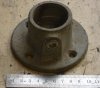
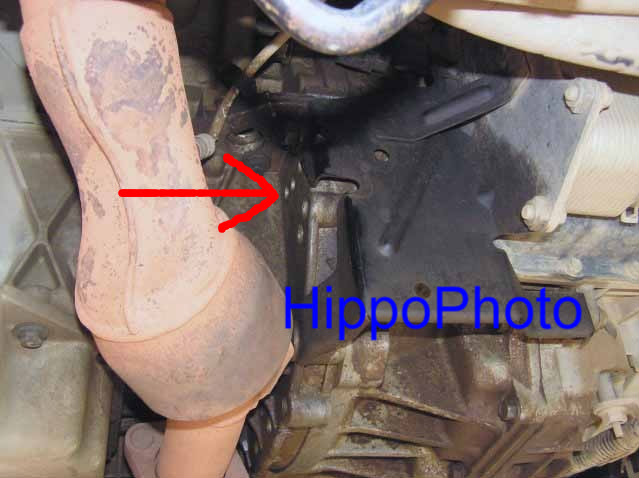
The flywheel locking pin slots in through a hole located on the lower front of the engine. You'll see it if you look up at the engine from the front. Pictured below:

rhElwVw.jpg

P7191068 rhElwVw

If you turn the crankshaft pulley bolt clockwise to line up the SAFE position, then check the alignment of the rear inlet and exhaust gear v-grove markers are inbound, then the correct safe position is found. If they're outbound, then rotate the crankshaft pulley clockwise by a further 360degrees. The correct SAFE position is now found if the rear inlet and exhaust gear v-grove markers are now inbound. The flywheel-locking pin should slot in. If it doesn't, turn the crankshaft pulley clockwise and anticlockwise slightly until it slots into the flywheel. You'll feel it slot in. There's several misleading studs on the flywheel, so once the flywheel locking pin is fitted, turn the crankshaft pulley clockwise and anticlockwise to make sure it doesn't move in either direction. If it does, you're up against a stud or in the wrong hole. Don't start the engine with this pin fitted.

Once you've undone and removed the crank shaft pulley bolt (22mm nut 160Nm) you'll probably need to remove the flywheel locking pin, in order to more accurately align the crank shaft pulley v-grove to the arrow on the oil pump housing, located at the rear of the crank shaft gear. Just remember which way you had to turned it, and by how much (only a little bit) so it makes it easier when assembling later on.

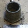
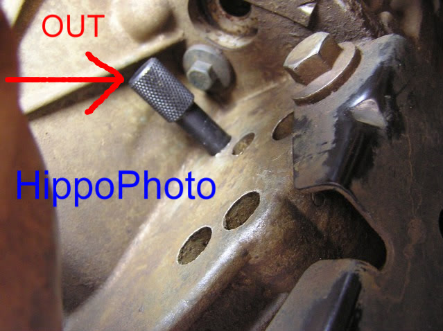
Fly wheel-locking pin pushed against the flywheel:

A1h0uaw.jpg

P8151269 A1h0uaw

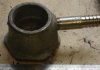
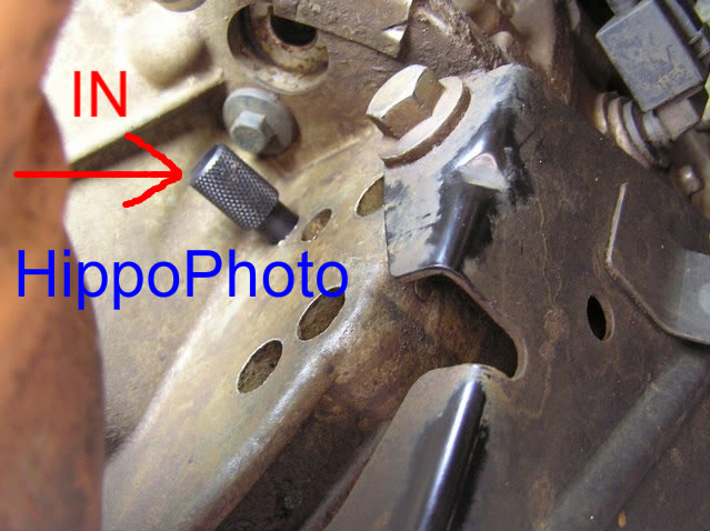
Flywheel locking pin fitted correctly:

C1x2kXB.jpg

P8151270 C1x2kXB

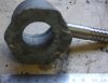
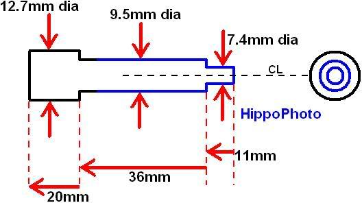
Fly wheel locking pin dimensions. The blue area is the section that slots in through the engine, into the flywheel:

GgxWv0r.jpg

Flywheellockingpin GgxWv0r
 
Last edited:
Back
Top