SWB re-chassis

This site contains affiliate links for which LandyZone may be compensated if you make a purchase.


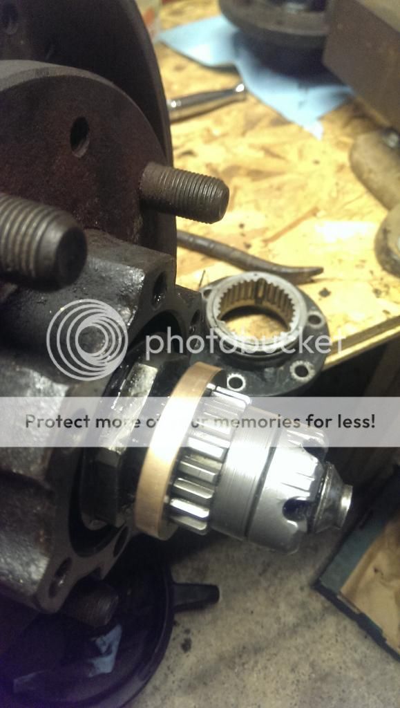
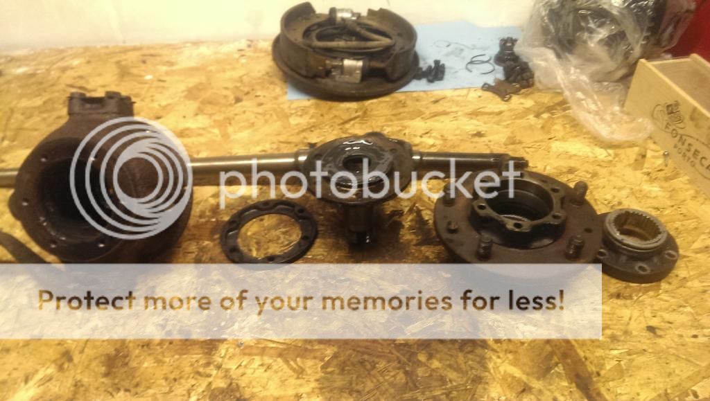
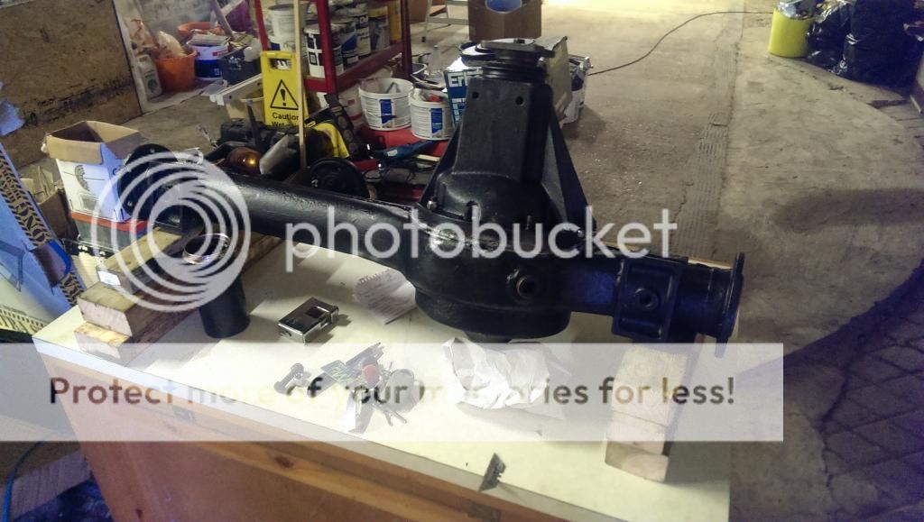
Drive flange came off leaving this. There was bits of a broken ring of some description too. Think it was part of the Fairey FWH.

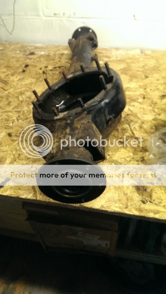
The shaft has about 5mm of freeplay, then stops dead. Researching into it, it sounds like the whole swivel has to come off at the union with the axle casing. Does that sound about right?
 
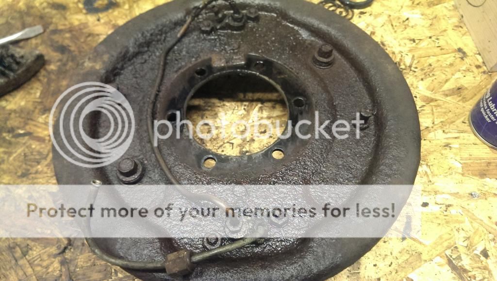
Ring of steel. The plastic strip came out of the FWH ok.
 
Last edited:
Success!

Looking through a few other resto threads, it appears you cant get the half shaft knuckle out of the stub axle, so I guess you have to take the whole steering assemble off at the axle if you cant get the funny nut of the end.

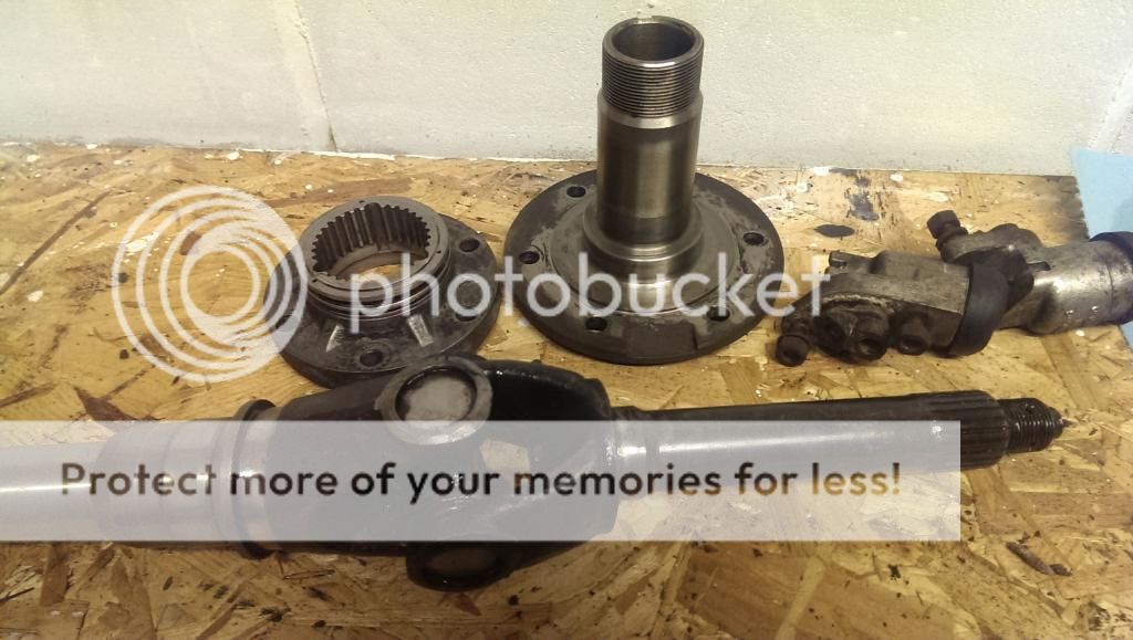
Anyway, a bit of ingenuity with the wrong sized spanners and an angle grinder left me with this lot to clean up and prep for reassemble.

I'll get some more pictures of the swivel balls but I dont think they will be reusable, but will await further advise from you lot :eek:


Update!

I've been working away on the front axle for some time and have made a bit of progress, and spent a fair bit on bearings, seals, nuts, bolts, swivel pins, balls...you name it. :eek:

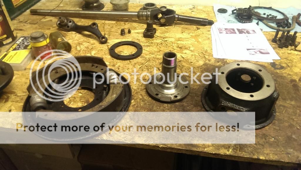
I've stripped all bits of the front axles down, degreased, wire brushed, primed and repainted. I'm now building it back up, even bought myself a spring balance for the swivel preload. :D


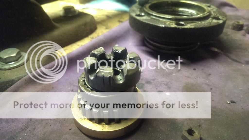
Here is the funny nut that was causing problems with the initial dismantle, along with the bearing/gear it retains. The spanner for my angle grinder is a good fit to apply torque to the nut, apart from the hole in the center is too small to fit over the end of the half shaft. I had to beast it off with a hammer in the end. I might ask an engineer chap I know to wittle something for me.


Here is the state of the existing swivel balls. Unfortunately they are pitted and were clearly leaking a lot of the oil/grease mixture from the outer swivel housing.


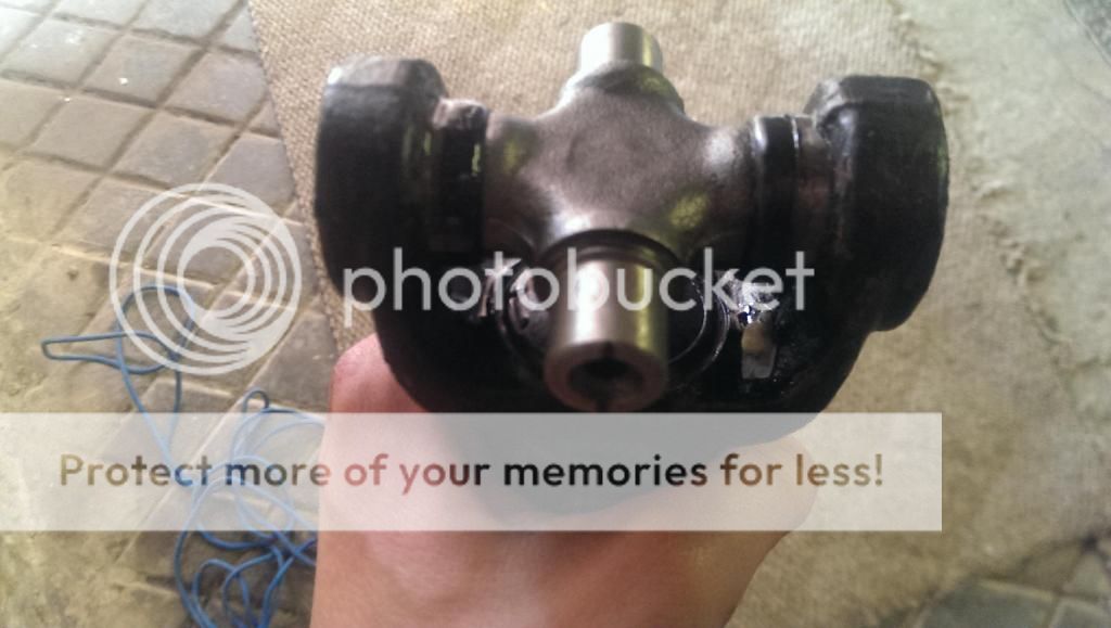
This a prop shaft yoke with what I believe are the correct replacement UJ spider. Something doesnt look right to me, like the caps protude too far in from the yoke and the spider itself should be wider to compensate. These are part number RTC3346 which everything suggests to be right. Can anyone shed any light here?


I have also rebuilt the front half shafts with new GKN UJ's. UJ's are actually quite straight forward once you have got the right technique which I didnt have when I attacked the props the first time and make a complete hash of it. Once I have got to the bottom of the correct UJ's to use I will have another go with a bit more confidence. :cool:

Finally, which way round does the seal in the back of the stub axle go? Took them out a while back and didnt take a picture - parts manual useless in this regard! :confused:

As ever, and comments/criticisms/advise gratefully received. Thanks for reading. (I'll try and get some more dynamic, action photos for next update!)
 
Assistance needed!

The short half shaft on front axle doesn't go in far enough! I've tried all sorts. its engaging with the diff, but still needs to go in another half inch or so. Other side looks ok.

Any suggestions? Thanks
 
Last edited:
No, wasn't a new bearing or collar. They are both in good condition so cleaned and regreased.

I'e given in a light persuasion with a leather hammer and its gone a bit futher but no struggling to get it out!:emps1:
 
not a good idea to persuade things through bearings where races are separate, rollers can dislodge , is seal collar new and larger diameter than brg race on shaft
 
ok, its in. Whether it will ever come out again is another matter.

Thanks for your help James. Its tight on the half shaft bearing.
 
no, it was the same bearing and collar. It feels and sounds smooth still. Fingers crossed. If it needs to come apart at some point in the future - such is life. Thanks again :)
 
no, it was the same bearing and collar. It feels and sounds smooth still. Fingers crossed. If it needs to come apart at some point in the future - such is life. Thanks again :)

seems ok then, once its done a few miles it wil probably come apart fairly easily :)
 
Ok, snail cam issue: 3 of the 4 adjusters on the front TLS set up throw the shoe off the cam (pushing the shoe outwards). I've tried moving the alignment posts in and out but it doesnt make any difference.

At the minute the brake system is not set up so there is no fluid in the slave cylinders. I wonder if the shoes come out of the slots in the pistons because the pistons doesnt follow the shoe as its moved out by the cam?

I've looked at the shoes and the cam posts are in the same place on each side so I dont think there is any issue with the the shoes being incorrectly fitted.

No pics i'm afraid as my phone has died :(
 
Just a thought - I found freewheel hubs to be more trouble than they were worth. Leaky, never engaged when you wanted them and the final straw was when I snapped one off on a rock on holiday in Cornwall. Might be worth going for the simplicity of plain drive members - and nuts with flats on!
 
Not sure how to tell as its all behind the shoe! Assuming you are looking at it perpendicular to the side of the vehicle... is that how you mean 'line up'?
 
you normally offer shoe up before fitting ,as you look from the side ,you should be able to see pin location from outer side and enough of cam
 
First, apologies for the delay in updating this thread - last update August 2014!

I ordered a new chassis from Richards, only 1 unfortunately :)
IMAG2484.jpg
IMAG2483.jpg

Galv prep prior to included mordant solution wash;
IMAG2486.jpg
and etch priming,
IMAG2487.jpg
followed by 2 coats of Chassis Black from Frosts.
IMAG2532.jpg

I have also got both front and back axles back together, although there is a bit more brake work to do, mostly getting the snail cams to work property, although this might wait until the rest of the system is back together.
IMAG2538.jpg

I ordered a set of GB Springs parabolics as my standard springs were pretty shot. 2 leaf front, 3 leaf rear is what they advise, which seems to tally with the advice on here.
IMAG2533.jpg

I got the springs on the axles and the assemblies back under the chassis
IMAG2544.jpg
IMAG2557.jpg

I have also fit a set of new Armstong standard dampers as they best suit my proposed use
IMAG2559.jpg

I looked in to various brake line kit options and Automec kept coming up. I thought they might have been a spurious Chinese outfit but they are actually UK based. Here is some of the axles lines in, the rest will have to wait until the bulkhead is fitted.
IMAG2738.jpg
IMAG2739.jpg

So, on to the bulkhead... It s not in bad nick to be fair, but needs new footwells. I got some from that bloke on ebay (Les someone... I cant find him now). They're pretty good, ribbed toe plates and reinforcing plate in the drivers footwell.
IMAG2547.jpg IMAG2546.jpg

So, the plan was to strip the bulkhead and get a local welder to get the new footwells in. Its looking like £400-£450 for this to happen, which I had resigned myself to. BUT, looking at this months Classic Land Rover mag they reference Classic Bulkheads http://shop.classicbulkheads.com/index.php?route=product/product&path=61_75&product_id=98 who can do a fully repaired and galv'd one for £675 on an exchange basis by the look of it. I then found Mosside Land Rovers (find them on Facebook) who look like a good outfit. I'm waiting to hear back on prices. The basic welding is more than I though it would be and a fully galv'd one isnt much more, so I'm thinking lets just do it properly. It is more money than expected, but that seems to be par for the course :confused:

Can you lot have a look at me bulkhead and let me know what you think? I think the door posts, top corners and vents are ok, but the paint work is looking pretty shabby. Not bad for 34 years old.

IMAG2779.jpg
IMAG2554.jpg IMAG2553.jpg
IMAG2552.jpg IMAG2551.jpg
IMAG2549.jpg IMAG2548.jpg
IMAG2550.jpg

New wiring loom required, and hopefully that will be the end of the big expenses. This thing is a bloody money pit :rolleyes::eek:
 
Back
Top