Diesel SWB Wiring questions

This site contains affiliate links for which LandyZone may be compensated if you make a purchase.

Webley1991

Well-Known Member
Posts
2,557
Location
London
Today I finally began threading some of the cables through to start re-installing the wiring for my Series 3. I am anticipating major problems here. I even got hold of a CO2 fire extinguisher in case anything decides to catch fire when it actually comes to running current through it.

I think I will have quite a few questions about this over the coming few weeks, so figured that I would keep everything in one thread.

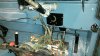
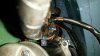
Firstly, where should the main taped bunch of cables coming from the instrument panel be routed? Above or below the steering column? See photo.

Thanks for any replies.
 

Attachments

  • s_col_wiring.jpg
    s_col_wiring.jpg
    279.6 KB · Views: 144
What.......... Both wires at the same time............... :D

I have just sorted the wiring on my series and it isnt that complicated. Nothing but a side light worked when I started and within a few evenings of head scratching and working out what wire did what it all came together nicely.

Im no electrician but managed to get everything working.

Run it along the top. Just under that weld at the top of the photo. It gets a bit tight behind the steering lock and it helps if you can grow your fingers a few inches. I have a book of new swear words if you run out, especially when working behind the clocks. :D
 
Here is the first problem. When I first got the vehicle, the horn switch wasn't wired up properly. The horn was connected to a toggle switch which was mounted on a hole drilled through the dashboard. I was told that the proper horn switch was faulty and it was bypassed as a quick fix.

Obviously I am planning on re-connecting the horn properly. I had a look at the horn switch today, and have some confusion with the wiring.

When I disassembled everything, the loose brown wire coming from the indicator switch assembly (photo 1) was connected to the spade crimp in the second photo. This brown wire is connected to the flasher unit. There are actually two flasher units behind the dashboard. One has three terminals and the other has two.

It seems that when I press the horn switch down, I get a poor circuit between the brown wire and the brown/black wire on the terminal block. If these two wires are the connections for the horn, why would one of them have been connected to a flasher unit?

Thanks for any suggestions.
 

Attachments

  • wiring_27615_1.jpg
    wiring_27615_1.jpg
    27.8 KB · Views: 92
  • wiring_27615_2.jpg
    wiring_27615_2.jpg
    55.4 KB · Views: 96
Brown wires are live - someone's just picked up a convenient live feed from the flasher. The horn should be fed from the battery side of fuse 1.
 
I'm not sure I'd just "fuse everything" a single fuse in the headlights circuit - if it blows, as is likely if a headlamp dies would leave you in the dark the small risk of fire is probably safer than the very likely risk of no lights whilst travelling at speed.

To fuse properly you would really need to split the wiring left/right for lighting.

The thing I don't understand is why the horn is unfused - I suppose you could describe it as a safety item. Though I'd say headlamp flash was more useful than horn in an emergency and that is fused.
 
I'm not sure I'd just "fuse everything" a single fuse in the headlights circuit - if it blows, as is likely if a headlamp dies would leave you in the dark the small risk of fire is probably safer than the very likely risk of no lights whilst travelling at speed.
.

oh, I hadn't thought of that, might take those off the box then
 
Here are a couple of questions from today:

Firstly, the manual shows the ignition switch with four terminals. Mine has five, or six if you count the extra one soldered to number five. What is the reason for this?

Secondly, there seems to be an unused terminal on the starter solenoid. I have connected the various brown wires to the threaded terminal, and thw white/red wire to the terminal marked "IGN". The red arrow shows the unused terminal. Should anyhting be connected to this?

Thanks for any replies.
 

Attachments

  • ign_rear.jpg
    ign_rear.jpg
    43.1 KB · Views: 87
  • s-sol_1.jpg
    s-sol_1.jpg
    144.8 KB · Views: 110
Thanks for the reply. I marked the wires up when I took them off, so they should have all gone back in the right places.

Someone had connected the bodged in horn switch to terminal 3 on my ignition switch. As of now, It won't have anything on it after reassembly as I am planning to wire the horn back up properly.
 
so are all the wires to things on 5 then?

I notice your 5 seems to have an extra connector soldered on to it.

forgot to say earlier that replacement bulkhead looks smart
 
Back
Top