1976 series 3 rebuild

This site contains affiliate links for which LandyZone may be compensated if you make a purchase.
Thanks for the nice comments, glad its useful for someone :)

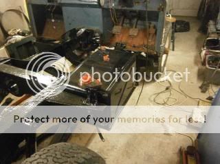
Right the fuel tank has also been refitted to the chassis and the dash was given a coat of black. This will get some soundproofing fitted before going back on.

P3250935.jpg


P3250936.jpg


We've also been working on the bulkhead. I know that footwells are a common thing that need replacing on old land rover so it may be beneficial to someone if I put the photos on here of how we did it.

The old footwell showing the rust that needs to be cut out
P3290938.jpg


The chassis was covered with a dust sheet to protect it when we were grinding
P3290946.jpg


Masking tape was used to mark where we were cutting out. Before cutting, it is important to measure everything using datum points to make sure you can cut the new footwell accurately.
P3290950.jpg


The part of the old footwell was cut out using a cutting disk in a grinder
P3290951.jpg


The old part of the foot well that was removed
P3290953.jpg


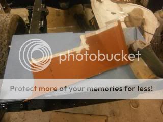
The new footwell, this was red oxided inside as it helps make scribe marks more clear
P3290954.jpg


The old footwell piece was placed in the new one and was scribed around to give us the basic outline shape to cut out, this gives the basic shape and leaves metal for adjustment later, especially if you mark out the piece oversize to this.
P3290955.jpg


P3290956.jpg


P3290957.jpg


Masking tape was placed along these lines to make it clearer where we were cutting. Arrows were drawn on the tape so we knew which side to cut and avoid any mistakes by cutting undersize

P3290958.jpg


The new part was then cut out of the footwell
P3290961.jpg


It was then offered up and because we had cut it oversize, needed adjustment to fit. Its better to cut oversize as you can trim it to give a good fit. Eventually we got it to fit like this

P3300962.jpg


P3300963.jpg


P3300964.jpg


The other footwell was pretty solid with only the corner having corroded. This was duly cut out
P3300965.jpg


Instead of cutting the metal out of the new passenger side footwell, we found an offcut of the other one and this was trimmed to fit.
P3300968.jpg


So tomorrow we shall have a go at the welding :)
 
Hi everyone, I've not been idle, just had a load of schoolwork to do so thats taken preference over updating here unfortunately. Anyway, the transfer box oil seal has been replaced and the gearbox is now finished and we've started work on the engine by taking off the head today.A lot of pictures and a proper update shall take place over the weekend :)

Sam
 
Right then, bit of a big update for you all now ;)

After the drivers side footwell was repaired we started work on the gearbox. It was put on top of an old trolley type thing to make it more comfortable to work on.

The cover plate over the gearbox was removed as we would need to be able to look inside to carry out the work. It was covered over again afterwards though (but not fastened) to prevent any dirt getting into the gearbox.

P4020982.jpg


The oil was then drained out of the overdrive into a clean plastic tub

P4020983.jpg


The nuts holding the overdrive to the gearbox were then removed. These nuts are threaded onto studs and a couple of the studs came out with them, nothing to worry about, the stud was held with a small pair of mole grips on the part with no thread which allowed the nut to be removed. To put the stud back into the gearbox, again we held it with the mole grips as it allowed me to tighten it up sufficiently.


The overdrive was removed by just pulling it back from the shaft. We discovered that the locking washer behind the mainshaft nut needed replacing.


To remove the mainshaft nut and the locking washer, you first need to use a punch to lift the locking tab from the nut, allowing it to be undone.


The nut was then undone by using a punch to undo it ( there is a special spanner for these nuts but we don't have one). To replace, the washer is put on the shaft, then the nut and the locking tab is punched over so it will prevent the nut from becoming undone.

The next job was to replace the rear oil seal from the transfer box as it was leaking. (The overdrive was left off as it meant there was a bit more room to work and we needed to get some gasket paper and hylomar). The first job was to remove the handbrake cover and then this nut


Behind the nut, on the end of the shaft there is afelt washer type thing, this was carefully removed as it could be reused.


The next job was to remove the hand brake assembly. The shoes are held in a recess by two very strong springs. A pry-bar was used to lever them up out of this recess, doing this means the springs can be removed and the shoes can be moved out of the way. The back plate was then also removed to give good access for removing the seal.


The oil seal was then removed. A new one was bought, we took the old one with to check it was the right one. To fit it back in the transfer box we placed it as square as possible and then tapped it into place by using a hammer and a piece of 2x1 (The wood is so that the hammer wouldn't hit anything metal and cause damage). It is important to work your way round the seal to make sure it goes in square.


With this job done, I removed various bits and pieces from the gearbox so they could be cleaned up and painted, these being the mounting brackets and the overdrive lever and bracket.


With the oil seal now replaced, it was possible to re-install the handbrake back plate.


I was also able to cut a new gasket for the overdrive out of some gasket paper


Hylomar was smeared around the gasket to give it a good seal (Both sides) and the overdrive was slid into place. (Befotre this though we had to trim the locking washer, the 2 spare locking tabs were preventing the overdrive from going on properly so they were cut of using a punch.


The overdrive cover plate was stripped of that red plate and given a coat of gloss black (the same paint as the chassis) Here it is replaced


The handbrake was then rebuilt. We found that the springs kept falling out of the handbrake shoes when we attempted to fit them so large split pins were used to prevent this. It was a struggle trying to extend the springs enough to fit the shoes correctly but we managed it in the end :)


The drum and the drum cover were then replaced


The parts I removed earlier were cleaned up and painted and here is the gearbox, all complete


More to follow...
 
Last edited:
Good work! Nice pictures and enjoying the thread :) I want a workshop like yours though! :cool:

Thank you :) Before the garage was built there was only a horrible little car port which my dad took great joy in knocking down :) Right, now for some more pictures and things:

First job when working on the engine was to remove the clutch by undoing the bolts that are located around it. These came off fairly easily


With that out of the way, the next task was removal of the flywheel which is a very heavy peace of kit. This was removed by the bolts in the centre. The yellow marker was on the clucth so that we knew which way to put it back on when it came to refitting. We also did the same to the flywheel but this time with a centre punch


To undo the bolts, you need to stop the flywheel from turning. We did this by using a pry bar against the teeth of the flywheel ring gear. The bolts are tight so we used a breaker bar. If anyone's wondering, this has to be done if the engine is going to be fitted to an engine stand.


After removing the flywheel, to be able to place the engine on a stand the flywheel cover needs to come off


Before removing, there was a bracket holding some wiring and piping near the fuel lift pump which was removed just to give a bit more access.


On this engine, the rear crankshaft oil seal was leaking so will be replaced. While we were at this stage it was decided to remove it.


With all that out of the way, we then bolted the engine to the engine stand


Unless anyone has any objections, I think I'll put the engine bits in the 2.5 N/A section as well as I don't think there's a rebuild thread in there at the minute. More pictures to come.
 
After the engine was bolted to the stand the first thing we did was to remove the fan, fanbelt and the alternator. The fan (a type of plastic on this) is bolted the water pump pully with 4 bolts which were pretty simple to undo once the fan was stopped from rotating.


This pipe was the next thing to be removed. To do this, all thatwas needed was to loosen the jubilee clip closest to the engine block


The engine mount brackets were then the next thing to be taken off (well the passenger side one at least, I left the other one for a while to do something else)


Next to be taken off was the inlet and exhaust manifold. These are 2 separate parts so if you undo all the bolts make sure one does not fall.


Some of the pipes were then removed as well as the plug for the alternator


Much better access to work now :)


The fuel filter was the next thing to go.


These hoses had to be removed before it could be taken off. When the hoses are taken off the pump, it is important to cover where the hoses fit on to the pump to stop dirt getting in as everything has to be clean.


The injector pipes were next. These were removed through the use of injection pipe spanner (like 3/4 of a ring spanner with an open end to slot over the pipe )


The heater control thing above the thermostat was next to go, this was undone with an adjustable spanner,


The next thing we did was to remove the injectors. To remove the injectors, the 2 bolts holding them to the block were removed and a brass drift was used to "lift" the injector up to be removed (it makes more sense in real life :) ). Before removal, the injectors were each numbered so we knew which injector belonged to each cylinder. The spill pipe running along the top of the injectors also has to be removed. Its worth noting that at the bottom of the injectors there is a copper washer, some came out with the injector but another was left in the hole.


Looking good! great thread, keep up the fab work and the pics, as you can guess pics are popular! :)

Thats just as well I have a load more pics :) Thanks for the nice comments :)

The next thing was the cylinder head, the first task being removal of the rocker cover, held on by 3 bolts.


A bit of thick string/ rope was passed around the rocker assembly to keep it all together. This didn't need to be taken apart so will stay like this and just be cleaned with paraffin.


The glow plugs were removed at this point to avoid damage


The pushrods were removed. It is important to keep them in the right order so a bit of cardboard numbered 1 to 8 and each pushrod pushed through by the corresponding number (1 being the front of the engine )


The cylinder head bolts were then cracked off by going round in opposites (it does say in the book which order to this in). They were first done with a breaker bar and then a ratchet and socket could be used.


Needless to say new gaskets will be purchased.
 
The thermostat was then removed. When it was replaced previously my granddad smeared copper grease around the studs which meant the bolts came out easily. I've heard of people having trouble with sheared bolts but I think doing this when it is replaced helps to stop bolts siezing.


The next thing was removing the valves. For this a valve spring compressor was used.


With the springs compressed, the collets could be removed. It is important to keep each component with the valve it came from and to keep the valves in order.


We found that the hotpoints (te part where the fuel comes through were cracked. To remove them we used a punch down the injector hole to push them out of the head surface.


Since the head was now disassembled, the head gasket was carefully scraped off and then the head was left in a large bucket of parrafin to help clean/ degrease it.

Whilst it was soaking it was decided to remove the old worn starter ring gear. The flywheel was held in the vice and a hacksaw used to cut through the gear making sure not to cut into the flywheel metal itself.


This was then placed on the floor and held upright. A sharp cold chisel was used on the cut made by the hacksaw and hit with a lump hammer. When doing this it is important to wear safety glasses so bits can't fly into your eyes as well as wrapping a cloth around where the cold chisel will strike, keeping the airborne parts low.
 
Next up the sump, all of the oil was drained out of this previously.


Its not too bad inside, just a small amount of thick oil in the bottom.


Inbetween jobs, I also decided to spray up the manifold with some High temperature silver.


The headgasket was again scraped off as well


Now for the removal of the pistons. The two big end bolts were removed.


The bearing shells are very worn, in need of replacement


The piston was then pushed up the bore using the rubber handle of a hammer so as to avoid causing any damage.


The crank looks good


All four pistons removed


Interesting to note, the engine has been rebored at some point in time with oversize pistons being fitted. All the parts should be here over the next week or so so more work on the engine to follow :)
 
While we're waiting for parts now a few other jobs have been done. The bulkhead has been repaired with new metal put in where it had started to corrode around the vent holes and it was then all painted in red oxide.


It was then painted in the same 2 pack paint as the chssis to hopefully give it a little more protection


The alternator was painted up and the box housing the heater matrix was dismantled to clean the matrix inside


The box is held together by small cross head screws


The matrix just slides out


Thank you so very mutch for this EPIC rebuild! through you, i´m living the dream i´ve had (and still have) for awhile.
Perhaps someday i´ll fulfill this dream of mine... till then, i´ll live it through you if you don´t mind!

Again, i profoundly thank you!
Cheers mate!
 
Haven't really done much due to my A-level exams, I finish school completely tomorrow after my final Physics exam so then I can crack on :) (And before anyone says anything I'm on my break from revising :) )
We'll start to rebuild the head over the weekend and measure the bores for new piston rings. Brake lines have started to be run and another job we'll start to do is run wires through the chassis
 
Possibly :)

When we get the piston rings the engine can go back together then that and the box can go back on then the tub and then it'll carry on going from there :) Should hopefully be back together in August :)

I'm aiming for end of june/early july :) probably less in-depth than yours but way more complications :doh:
 
Back
Top