- Posts
- 83,230
- Location
- Embasinga stocæ
Some time ago I fitted a low coolant alarm to my GT40. My version just had a simple switch to warning light, but suffers from false alarms as the coolant sloshes around in the header tank. As this has been recently discussed on the form, I have written this up, most of which has been blatantly plagiarized from an Aussie forum and then anglicized and includes instruction on how to fit a "slugging circuit" so that it does not react quite so quickly, but quick enough if you have problems - ideal for Freelander owners..
In our Land Rover engines, the water pump draws coolant in through the bottom radiator hose and pushes the coolant from this hose up through the engine and out through the thermostat housing into the top radiator hose. If the coolant level was low it will show up in both the radiator and the expansion tank, before a low level was experienced in the thermostat housing or top radiator hose (whilst the water pump is operating). It would only be when the pump was stopped that the low coolant level would be equal in both the expansion tank, thermostat housing and radiator. This is in fact done deliberately by most manufacturers to ensure that the engine receives its full level of coolant whilst in operation, even if the system is a little low. The low level is carried in the radiator, not in the engine. Only when the level is so low that it falls below the level of the water pump (causing the pump to cavitate) will the engine not be full of coolant whilst the pump is operating.
This is the system for the majority of engines. A very few have a reverse coolant flow where the thermostat is mounted below the water pump, and the pump pushes coolant down into the bottom radiator hose, up through the radiator and into the engine. In this system coolant level is ultra critical because any low level is carried in the engine (at cylinder head level) and the radiator will always remain full whilst the pump is in operation.
The expansion tank is the most convenient of the correct places to install a sensor and some people will go down the route of using one of those Range Rover caps that incorporated a level sensor. However, the Rangie cap sensor has proved to be quite temperamental, so a more reliable solution is needed. Enter the simple and effective float switch to be found on Welcome to rswww.com - pn 317-932. - here.
Here’s the coolant level sensor, a straightforward level switch, easy to install with minimal chance of gremlins:

Installing the switch was easy, simply drill a 23mm hole in the side of the plastic expansion tank, screw in the sensor and wire it up:

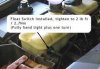
Here it is installed in a 200tdi Defender:

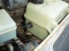
Here’s one installed in a TD5:

And another one in a Series II Disco:

The sensor is just a switch, and as it is it’d work fine in an on-road vehicle, but our vehicles may occasionally spend some time at a slight angle, or bouncing around a bit. This would inevitably lead to false alarms as the coolant sloshes around in the tank giving the sensor a hard time. Obviously what is needed is some sort of time delay. At this point I copied the circuit from the Aussie forum. They put together a simple and robust little circuit from fairly commonly available components that achieves our objective i.e., a short (adjustable) delay before the alarm is triggered to prevent false signals when off road.
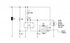
Firstly, here’s the circuit diagram:

Finally, here’s the description of the circuit for those of you who wish to replicate it:
This circuit is setup to provide an adjustable delay from the sensor located in the header tank when the level drops.
It works using a basic 555ic timer circuit. When the ignition source is initially turned on pin 2 is triggered via a short pulse from the C2 and R2 combination. This then allows C1 to charge via VR1 and R1. If the tank switch is closed (the tank is full) C1 is held to ground and a small current flows through R1,VR1 and the tank switch.
This will remain like this until the tank switch is opened or the ignition is turned off.
In the event that the tank switch opens C1 will begin to charge through VR1 and R1. When C1 gets to 60% of the ignition voltage pin 3 on the 555ic will be grounded causing Rly1 to turn on and sound the alarm or light a warning light.
A suppressor was added inline with the supply to prevent false alarms when heavy load equipment is started and stopped. This was typically fans and windscreen wipers.
A good starting point is to set for about 8 seconds of delay. The components used are very easily found (from Maplins) and seem to give a good range and do not draw much current through the tank switch.
Component list
S1 - Suppressor
R1 – 33k
R2 – 33k
VR1 - 1M
C1 - 4.7 uf
C2 - value unsure but not that critical
D1- IN4001
Rly1 - Standard 12volt relay
In our Land Rover engines, the water pump draws coolant in through the bottom radiator hose and pushes the coolant from this hose up through the engine and out through the thermostat housing into the top radiator hose. If the coolant level was low it will show up in both the radiator and the expansion tank, before a low level was experienced in the thermostat housing or top radiator hose (whilst the water pump is operating). It would only be when the pump was stopped that the low coolant level would be equal in both the expansion tank, thermostat housing and radiator. This is in fact done deliberately by most manufacturers to ensure that the engine receives its full level of coolant whilst in operation, even if the system is a little low. The low level is carried in the radiator, not in the engine. Only when the level is so low that it falls below the level of the water pump (causing the pump to cavitate) will the engine not be full of coolant whilst the pump is operating.
This is the system for the majority of engines. A very few have a reverse coolant flow where the thermostat is mounted below the water pump, and the pump pushes coolant down into the bottom radiator hose, up through the radiator and into the engine. In this system coolant level is ultra critical because any low level is carried in the engine (at cylinder head level) and the radiator will always remain full whilst the pump is in operation.
The expansion tank is the most convenient of the correct places to install a sensor and some people will go down the route of using one of those Range Rover caps that incorporated a level sensor. However, the Rangie cap sensor has proved to be quite temperamental, so a more reliable solution is needed. Enter the simple and effective float switch to be found on Welcome to rswww.com - pn 317-932. - here.
Here’s the coolant level sensor, a straightforward level switch, easy to install with minimal chance of gremlins:
Installing the switch was easy, simply drill a 23mm hole in the side of the plastic expansion tank, screw in the sensor and wire it up:
Here it is installed in a 200tdi Defender:
Here’s one installed in a TD5:
And another one in a Series II Disco:
The sensor is just a switch, and as it is it’d work fine in an on-road vehicle, but our vehicles may occasionally spend some time at a slight angle, or bouncing around a bit. This would inevitably lead to false alarms as the coolant sloshes around in the tank giving the sensor a hard time. Obviously what is needed is some sort of time delay. At this point I copied the circuit from the Aussie forum. They put together a simple and robust little circuit from fairly commonly available components that achieves our objective i.e., a short (adjustable) delay before the alarm is triggered to prevent false signals when off road.
Firstly, here’s the circuit diagram:
Finally, here’s the description of the circuit for those of you who wish to replicate it:
This circuit is setup to provide an adjustable delay from the sensor located in the header tank when the level drops.
It works using a basic 555ic timer circuit. When the ignition source is initially turned on pin 2 is triggered via a short pulse from the C2 and R2 combination. This then allows C1 to charge via VR1 and R1. If the tank switch is closed (the tank is full) C1 is held to ground and a small current flows through R1,VR1 and the tank switch.
This will remain like this until the tank switch is opened or the ignition is turned off.
In the event that the tank switch opens C1 will begin to charge through VR1 and R1. When C1 gets to 60% of the ignition voltage pin 3 on the 555ic will be grounded causing Rly1 to turn on and sound the alarm or light a warning light.
A suppressor was added inline with the supply to prevent false alarms when heavy load equipment is started and stopped. This was typically fans and windscreen wipers.
A good starting point is to set for about 8 seconds of delay. The components used are very easily found (from Maplins) and seem to give a good range and do not draw much current through the tank switch.
Component list
S1 - Suppressor
R1 – 33k
R2 – 33k
VR1 - 1M
C1 - 4.7 uf
C2 - value unsure but not that critical
D1- IN4001
Rly1 - Standard 12volt relay
Attachments


Last edited:
