Griffdowg
New Member
- Posts
- 7,194
- Location
- Somewhere in Bristol
Right, This is my 1st attempt at a guide aimed to help you fit a 2nd fuel tank between the chassis rails at the back of an earlier (pre TD5) 90.
If you cannot use a grinder, weld or get someone to fabricate parts its a non-starter, so dont bother reading on. Also note this is almost a completely fabricated system, nothing is set in stone or exact, you WILL have to use your own ingenuity (power of creative imagination) to make the system work and work well. This guide applies to my 300TDI, earlier models may vary so you may need different exhaust parts and the brackets will likely be different. Also note that I bought this all off another forum member (lucky me) so did not have to make/source the brackets, filler or anything else. It was all (almost) to hand.
A basic run down of the steps:
Part 1 will deal with steps 1-4 with Part 2 taking care of 5-6
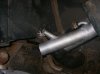
Firstly the TD5 tank sits right were a 300TDI rear silencer is, so the 1st step is to move the Exhaust. I went for a side exit custom fabrication but you can use later TD5 parts. According to other sources, these are:
ESR4526 (silencer)
ESR4527 (tailpipe)
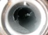
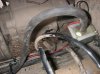
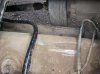
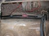
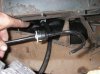
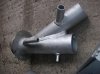
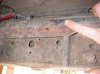
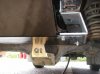
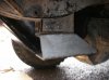
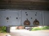
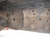
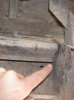
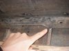
2nd step is to cut the triangular fillet out of the rear cross member. The TD5 cross members have a flat face allowing the tank to recess up flush against it. Earlier ones are not like this. Photo's 1-3 show you where you need to cut and photo 4 shows the section cut out. I had to cut it into 4 sections in the end and do lots of hammering with a chisel to get the thing out. Its not pretty, but it works. Photo 5 shows it primered with my recovery ring (ooo errrr) re attached. Note. If you have a towing assembly or similar this may not work, or you may need to upgrade to a TD5 tow pack. This may also cause problems with not having the right mounts.
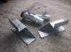
So now your vehicle is ready to accept the tank") The 3rd step and probably the most time consuming is getting the brackets fabricated. The brackets I have are made to be fixed to the anti roll bar mounts on the chassis rail, again earlier models may vary. You will need to find a way of attaching (or welding) on brackets in this area to hold the Tank. This is where each vehicle will vary throughout the range. Photo 6 shows the brackets a Y piece filler. The filler has been made from a standard filler and a TD5 filler. The reason being the breather pipes are the correct diameter. On the otherside of the standard filler piece is a small diameter pipe which is angled at 90 degree's down the filler. This is how the fuel is transfered from 1 tank to the other.
The 3rd step and probably the most time consuming is getting the brackets fabricated. The brackets I have are made to be fixed to the anti roll bar mounts on the chassis rail, again earlier models may vary. You will need to find a way of attaching (or welding) on brackets in this area to hold the Tank. This is where each vehicle will vary throughout the range. Photo 6 shows the brackets a Y piece filler. The filler has been made from a standard filler and a TD5 filler. The reason being the breather pipes are the correct diameter. On the otherside of the standard filler piece is a small diameter pipe which is angled at 90 degree's down the filler. This is how the fuel is transfered from 1 tank to the other.
There are varying options and opinions here in that you could opt for a simple 12v fuel transfer pump system (which is what i have installed) or go for a valve change over system such as a pollak valve which are a little more complicated to set-up and will need the original system interfered with. Also instead of fabricating a Y piece filler, you could cut the bodywork at the rear and install a seperate filler (like a TD5 90). There are many options and it is worth thinking about.
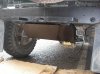
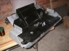
Step 4, The fuel tank arrangments. firstly you need to source a TD5 90 tank (WHK10040). they come up on ebay alot but make sure its for a 90 all the others will not fit secondly the cradle (WFI100070) thirdly the sender unit (WQB100430) then the sealing ring, adapter, and metal ring for fitting this sender in the tank (ESR 3806/ ESR 3807/ ESR 3808). Lastly its worth investing in a fuel tank guard from the likes of simmonites, rebel, paddocks etc. Offer this up and it should all fit snugly underneath, you will also have to remove the towing/lashing rings from the chassis because they will interfere with the installation. Prior to installing the unit make sure all your pipework is secure and that your sender unit is working. Also note the return on the sender will need to be blocked off IF you are using a fuel transfer system. Photos 7-10 show the tank install arrangement.
Right thats Part 1 over. Now go make a cup of tea before reading part 2 :blabla:
G
If you cannot use a grinder, weld or get someone to fabricate parts its a non-starter, so dont bother reading on. Also note this is almost a completely fabricated system, nothing is set in stone or exact, you WILL have to use your own ingenuity (power of creative imagination) to make the system work and work well. This guide applies to my 300TDI, earlier models may vary so you may need different exhaust parts and the brackets will likely be different. Also note that I bought this all off another forum member (lucky me) so did not have to make/source the brackets, filler or anything else. It was all (almost) to hand.
A basic run down of the steps:
- Move Exhaust
- 2. Cut Rear Cross Member
- 3. Fabricate Brackets &/or Filler
- 4. Fit Tank/Cradle/Guard
- 5. Plumb in Transfer Pump
- 6. Wire up Switch/Gauge/Sender
Part 1 will deal with steps 1-4 with Part 2 taking care of 5-6
Firstly the TD5 tank sits right were a 300TDI rear silencer is, so the 1st step is to move the Exhaust. I went for a side exit custom fabrication but you can use later TD5 parts. According to other sources, these are:
ESR4526 (silencer)
ESR4527 (tailpipe)
2nd step is to cut the triangular fillet out of the rear cross member. The TD5 cross members have a flat face allowing the tank to recess up flush against it. Earlier ones are not like this. Photo's 1-3 show you where you need to cut and photo 4 shows the section cut out. I had to cut it into 4 sections in the end and do lots of hammering with a chisel to get the thing out. Its not pretty, but it works. Photo 5 shows it primered with my recovery ring (ooo errrr) re attached. Note. If you have a towing assembly or similar this may not work, or you may need to upgrade to a TD5 tow pack. This may also cause problems with not having the right mounts.
So now your vehicle is ready to accept the tank
The 3rd step and probably the most time consuming is getting the brackets fabricated. The brackets I have are made to be fixed to the anti roll bar mounts on the chassis rail, again earlier models may vary. You will need to find a way of attaching (or welding) on brackets in this area to hold the Tank. This is where each vehicle will vary throughout the range. Photo 6 shows the brackets a Y piece filler. The filler has been made from a standard filler and a TD5 filler. The reason being the breather pipes are the correct diameter. On the otherside of the standard filler piece is a small diameter pipe which is angled at 90 degree's down the filler. This is how the fuel is transfered from 1 tank to the other.There are varying options and opinions here in that you could opt for a simple 12v fuel transfer pump system (which is what i have installed) or go for a valve change over system such as a pollak valve which are a little more complicated to set-up and will need the original system interfered with. Also instead of fabricating a Y piece filler, you could cut the bodywork at the rear and install a seperate filler (like a TD5 90). There are many options and it is worth thinking about.
Step 4, The fuel tank arrangments. firstly you need to source a TD5 90 tank (WHK10040). they come up on ebay alot but make sure its for a 90 all the others will not fit secondly the cradle (WFI100070) thirdly the sender unit (WQB100430) then the sealing ring, adapter, and metal ring for fitting this sender in the tank (ESR 3806/ ESR 3807/ ESR 3808). Lastly its worth investing in a fuel tank guard from the likes of simmonites, rebel, paddocks etc. Offer this up and it should all fit snugly underneath, you will also have to remove the towing/lashing rings from the chassis because they will interfere with the installation. Prior to installing the unit make sure all your pipework is secure and that your sender unit is working. Also note the return on the sender will need to be blocked off IF you are using a fuel transfer system. Photos 7-10 show the tank install arrangement.
Right thats Part 1 over. Now go make a cup of tea before reading part 2 :blabla:
G
Attachments
-
 1.jpg214.7 KB · Views: 2,931
 -
 10.jpg152.4 KB · Views: 2,676
 -
 9.jpg165.3 KB · Views: 2,613
 -
 8.jpg241.6 KB · Views: 2,813
 -
 7.jpg204.7 KB · Views: 2,870
 -
 6.jpg239.9 KB · Views: 2,586
 -
 5.jpg152.9 KB · Views: 2,960
 -
 4.jpg151.4 KB · Views: 2,546
 -
 3.jpg197.6 KB · Views: 2,870
 -
 2.jpg128.6 KB · Views: 2,491