From Rave ... Hope it helps ...
")
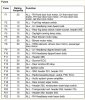
"INTRODUCTION
The fuses are mounted in four fuse boxes; one in the right hand side of the
engine compartment, one in the passenger compartment, under the fascia
below the steering wheel, and a satellite fuse box is located under each front
seat.
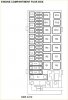
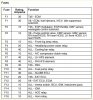
The engine compartment fuse box contains high current screw-in fuses, which
feed multiple circuits, smaller pull-out type fuses, and relays. A 150 Amp fusible
link is included to protect the alternator.
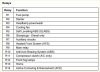
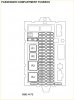
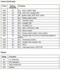
The passenger compartment fuse box contains the smaller pull-out type fuses
and relays.
The two satellite fuse boxes each contain three pull-out type fuses and protect
the seat motors.
On vehicles with rear air conditioning fitted, a 40 Amp in-line fuse is located
behind the LH rear quarter trim panel, taped to the harness. The in-line fuse
protects the resistor pack used for rear blower motor speed operation. Failure
of the fuse will prevent blower operation in speeds 1, 2 and 3. The fastest
speed 4 will still operate when the fuse has failed."
Heated Rear Window (HRW)
Heated Rear Window Description
The HRW is operated from a non-latching switch located to the left of the
instrument pack. The switch has an indicator light to show when the HRW is
operating. The HRW element comprises fourteen metallic strips bonded to the
inside surface of the rear window. The HRW will only function when the engine
is running due to the high current draw and subsequent load on the battery.
The HRW can also be operated by the air temperature control ECU on vehicles
fitted with air conditioning.
When the HRW is selected on, heater elements in the door mirror glass also
operate. Refer to Mirrors - Description and Operation in this manual for details.
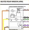
Heated Rear Window Supply
Circuit supply
A feed from the battery positive terminal is connected by an R wire to the
engine compartment fusebox, where it passes through fusible links 1, 6, 8 and
fuse 13. Fusible links 1 and 6 are connected in series.
A feed from fusible links 1 and 6 is connected from the engine compartment
fusebox to the passenger compartment fusebox on an S wire, where it passes
through fuse 8 and is connected to the contacts of the heated rear screen
relay.
A feed from fuse 13 in the engine compartment fusebox is connected on a PN
wire to the Body Control Unit (BCU).
A second feed from fuse 13 is connected on a PN wire to the passenger
compartment fusebox and is connected to the coil of the heated rear screen
relay.
A feed from fusible link 8 in the engine compartment fusebox is connected on
an NW wire to the passenger compartment fusebox and from the fusebox to
the ignition switch on an N wire.
Ignition switch supply
When the ignition switch is in position II, the feed from fusible link 8 flows
through the ignition switch to the passenger compartment fusebox on a Y wire.
The feed continues through fuse 29 in the passenger compartment fusebox
and is connected to the BCU on a GU wire.
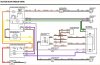
Heated Rear Window Switch Operation
When the HRW switch is operated, an earth path is completed from the HRW
switch to earth header C0017 LHD/C0018 RHD on a B wire, via header C0760.
The completion of the earth path from the HRW switch, completes an earth
path from the BCU to the switch on an NB wire. The earth path completes a
circuit within the BCU for an internal electronic switch which receives its feed
from fuse 29 in the passenger compartment fusebox.
The internal switch closes, completing a circuit which allows the feed from fuse
13 to flow through the internal switch, then to the HRW switch on an NP wire.
The feed illuminates the HRW switch indicator light and is earthed from the
switch to earth header C0017 LHD/C0018 RHD on a B wire, via header C0760.
The feed from fuse 29 is connected to a second internal switch within the BCU.
When the HRW switch is operated, the completed earth path closes the
internal switch. This completes an earth path from the coil of the heated rear
screen relay, through the Intelligent Drivers Module (IDM) and from the
passenger compartment fusebox to the BCU on an SK wire, via header
C0293 LHD/C0292 RHD. This connection is the serial data bus between the
IDM and the BCU.
The BCU earth is connected from the BCU to earth header C0551 on a B wire.
The IDM is also connected to earth header C0551 on a B wire from the
passenger compartment fusebox.
The completed earth path energises the heated rear screen relay, closing the
contacts and allowing the feed from fuse 8 in the passenger compartment
fusebox to flow through the contacts.
The feed flows from the passenger compartment fusebox to the rear screen
heater element on an NP wire.
The rear screen heater element is connected to earth header C0706 on a B
wire.
The momentary operation of the non-latching HRW switch, signals internal
electronic switches within the BCU to close. Internal circuitry within the BCU
holds the switches closed for a pre-determined period or until the HRW switch
is pushed a second time.
Air Temperature Control (ATC) ECU Operation
On vehicles fitted with air conditioning, the HRW can be operated when DEF,
feet/screen or screen is selected on the ATC control panel.
When one of the above selections is made, the ATC ECU provides a feed to
the HRW switch into the NP wire from the BCU to the HRW switch. This
illuminates the switch indicator light.
Simultaneously, the ATC ECU also provides an earth path into the NB wire
from the BCU to the HRW switch. This earth path allows the internal electronic
switches within the BCU to close, powering the rear screen heater element as
described previously.